CAMPAIGN:UNDERTORQUED TRANSMISSION TO ENGINE

SUBJECT: UNDER TORQUED TRANSMISSION TO ENGINE AND/OR TRANSMISSION TO CLUTCH HOUSING BOLTS
Models: 1994 Chevrolet S-10 and 1994 GMC Sonoma Pickups
TO: ALL GENERAL MOTORS DEALERS
General Motors of Canada Limited has determined that certain 1994 Chevrolet S-10 Pickups and 1994 GMC Sonoma Pickups built at Linden Assembly and equipped with 2.2L engines (LN2) may have transmission-to-engine bolts tightened below the specified torque. On vehicles equipped with an automatic transmission (M30), any of the six bolts that attach the transmission to the engine may be affected. On vehicles equipped with a manual transmission (MW1), any of the six bolts that attach the bell housing to the engine, as well as the four bolts that attach the transmission to the bell housing, may be affected. This "low torque" condition could cause very noticeable driveline disturbance. If the operator failed to heed this warning, further damage could occur, including transmission case fracture and possible fluid leaks, transmission torque converter, pump, or clutch damage, loss of drive, or the inability to disengage the clutch.
To correct this condition, dealers are to properly torque the transmission-to-engine and/or transmission-to-clutch housing bolts.
VEHICLES INVOLVED:
Involved are certain 1994 Chevrolet S-10 Pickups and 1994 GMC Sonoma Pickups produced at Linden Assembly Plant and built within the following VIN breakpoints:
Year Model Plant Plant Code From Through
1994 Chevrolet S-10 Linden K SOP RK156386 1994 GMC Sonoma Linden K SOP RK516988
NOTE: PLEASE CHECK DCS SCREEN 45 OR YOUR V.I.N. LISTING BEFORE PERFORMING CAMPAIGN TO ENSURE THAT THE VEHICLE IS AFFECTED. ONLY AFFECTED VIN'S WILL BE PAID.
All affected vehicles have been identified by the VIN listing provided to involved dealers with this bulletin. Any dealer not receiving a listing was not shipped any of the affected vehicles.
DEALER CAMPAIGN RESPONSIBILITY:
All unsold new vehicles in dealer's possession and subject to this campaign must be held and inspected/repaired per the Service Procedure of this Campaign Bulletin before owners take possession of these vehicles.
Dealers are to perform this campaign on all involved vehicles at no charge to owners, regardless of kilometers traveled, age of vehicle, or ownership, from this time forward.
Owners of vehicles recently sold from your new vehicle inventory with no owner information indicated on the dealer listing, are to be contacted by the dealer, and arrangements made to make the required correction according to instructions contained in this bulletin. This could be done by mailing to such owners a copy of the owner letter accompanying this bulletin. Campaign follow- up cards should not be used for this purpose, since the owner may not as yet have received the notification letter.
In summary, whenever a vehicle subject to this campaign is taken into your new or used vehicle inventory, or is in your dealership for service in the future, please take the steps necessary to be sure the campaign correction has been made before selling or releasing the vehicle.
CAMPAIGN PROCEDURE:
Refer to Section 4 of the Service Policies and Procedures Manual for the detailed procedure on handling Product Campaigns. Dealers are requested to complete the campaign on all transfers as soon as possible.
OWNER NOTIFICATION:
All owners of record at the time of campaign release are shown on the attached computer listing and have been notified by first class mail from General Motors (see copy of owner letter included with this bulletin). The listings provided are for campaign activity only and should not be used for any other purpose.
PARTS INFORMATION:
Parts are not required to complete this campaign.
PARTS AND LABOUR CLAIM INFORMATION:
Credit for the campaign work performed will be paid upon receipt of a properly completed campaign claim card or DCS transmission in accordance with the following:
Repair Code Description Time Allowance ----------- ----------- -------------- 2A Torque Bolts 1.1
Labour Op $ Allowance --------- ----------- T2501 Customer Vehicle Wash $8.00
Time allowance includes 0.1 hour for dealer administrative detail associated with this campaign for Repair Code 2A.
SERVICE PROCEDURE:
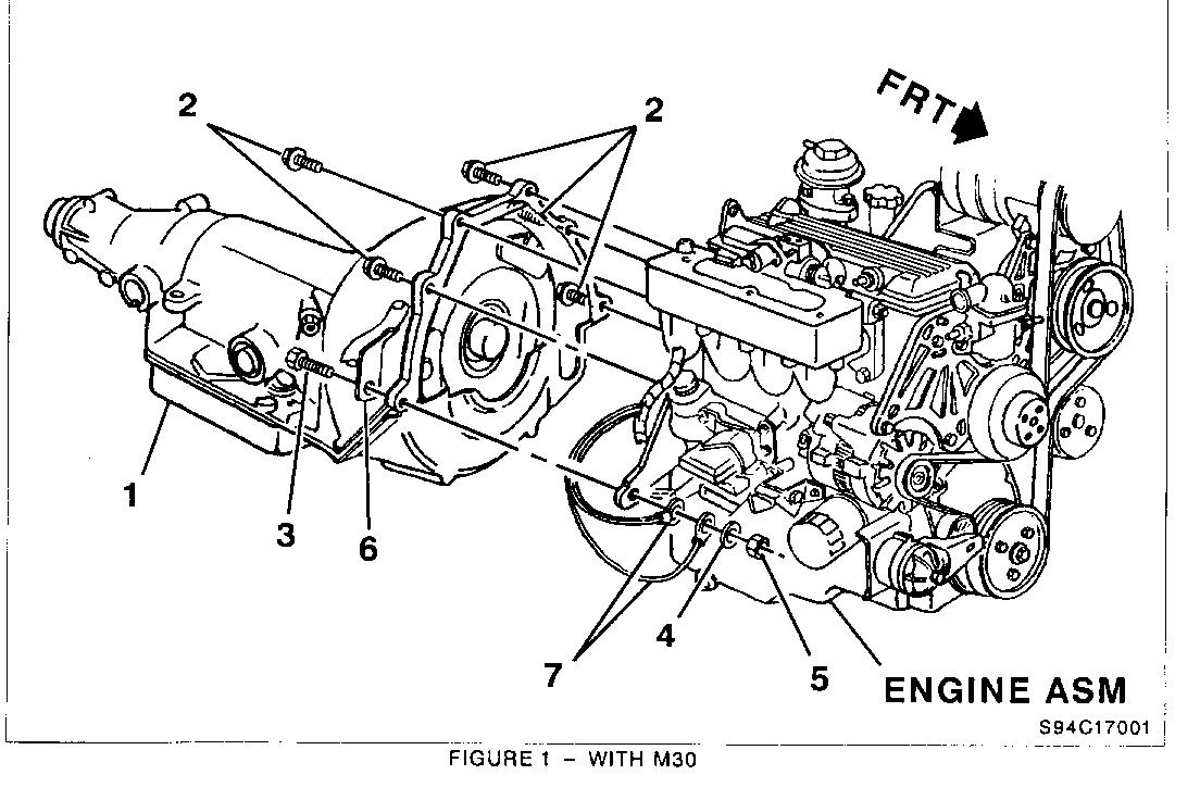
For vehicles equipped with the 2.2L engine and 4L60E (RPO M30 Figure 1, Item 1) automatic transmission, perform the following procedure:
1. Move gear selector to LOW "1."
2. Raise vehicle.
3. Disconnect exhaust hangers (2 or 3 depending on wheelbase) and lower exhaust system.
4. Remove fuel line bracket at crossmember (1 bolt).
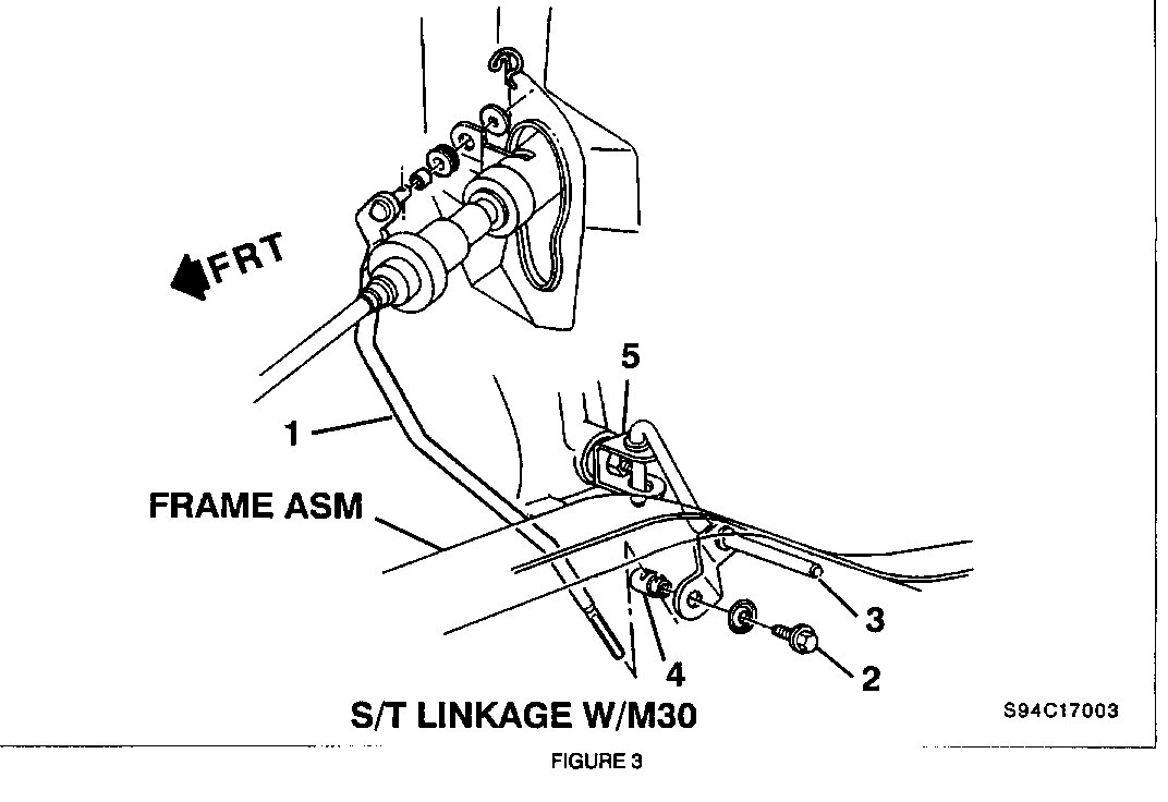
5. Remove transmission control lever (Figure 3, Item 3) from transmission shift lever, (Figure 3, Item 5), (1 cotter pin).
6. Position transmission jack under transmission.
7. Remove 3 left side transmission crossmember bolts.
8. Remove 4 right side transmission crossmember bolts.
9. Remove transmission mount nut and crossmember from vehicle.
10. Lower transmission (Figure 1, Item 1) as required to access transmission attaching bolts.
11. Torque 5 transmission-to-engine bolts (Figure 1, Item 2) using a 28" extension, to 90 N.m (66 lb. ft.).
12. Torque nut (Figure 1, Item 5) on lower right side transmission-to-engine bolt (Figure 1, Item 3) to 90 N.m (66 lb. ft.).
13. Raise transmission to the proper installation position.
14. Install crossmember and torque 3 left side and 4 right side bolts to 54 N.m (40 lb. ft.).
15. Torque transmission mount nut to 45 N.m (33 lb. ft.).
16. Remove transmission jack.
17. Install transmission control lever (Figure 3, Item 3) to transmission shift lever (Figure 3, Item 5) and fasten (1 cotter pin).
18. Install fuel line bracket at transmission crossmember and torque to 17 N.m (13 lb. ft.).
19. Reconnect exhaust hangers and torque fasteners to 25 N.m (18 lb. ft.).
20. Adjust linkage using the following procedure:
Adjustment procedure applies to vehicles w/4L60E transmission.
a) Linkage adjustment must be performed at the transmission prior to any "PRNDL" indicator adjustment at the steering column.
b) Full weight of vehicle must be on wheels (curb height). Do not use a frame hoist to raise the vehicle for this procedure. Mandatory that vehicle be raised on a twin post hoist or utilize an alignment rack.
c) Position the steering colunm shift in the neutral gate notch. (Do not use the indicator to find neutral.)
d) Loosen the bolt (Figure 3, Item 2) in the swivel (Figure 3, Item 4) that clamps the shift rod (Figure 3, Item 1) to the transmission equalizer lever (Figure 3, Item 3). Make sure that the shift rod moves freely in the swivel.
e) Set trans lever (Figure 3, Item 5) in neutral detent. Obtain neutral detent by indexing trans lever all the way clockwise to "PARK," then counter-clockwise two detents to "NEUTRAL." (Alternate procedure is rotate trans lever counter-clockwise all the way to "L1," then rotating it clockwise four detents.)
f) Make sure that trans control lever (Figure 3, Item 3) is fully seated in trans lever (Figure 3, Item 5). Hold the rod (Figure 3, Item 1) tightly in the swivel (Figure 3, Item 4). Tighten clamp screw (Figure 3, Item 2) against rod (Figure 3, Item 1) to 25 N.m (18 lbs. ft.). Make sure the rod does not move in the swivel while tightening the screw.
g) Verify proper adjustment:
0 When moving the transmission shift lever in either direction, all detent positions will be attainable without a binding condition present.
0 With the key on and the shift lever in "Reverse," the key will not be removable and the steering column will not be locked.
0 With the key in the lock position and the shift lever in the "Park" position, the key will be removable, the steering wheel will be locked, and the shift lever will not disengage "Park." In addition, verify that the vehicle is held stationary in "Park."
0 The engine must start in the "Neutral" or "Park" positions only. Adjust neutral safety switch as required.
0 Verify that shift indicator position matches actual transmission range. Adjust "PRNDL" switch as required.
21. Lower vehicle.
22. Return gear selector to "PARK."
23. Apply the Campaign Identification Label.
24. Wash customer's vehicle.
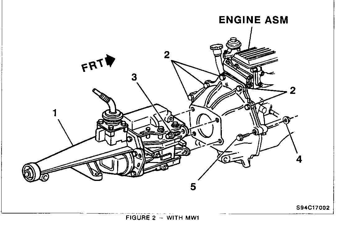
For vehicles equipped with the 2.2L engine and 5-speed (RPO MW1 Figure 2, Item 1) manual transmission, perform the following procedure:
1. Place shift lever in neutral.
2. Raise vehicle.
3. Disconnect exhaust hangers (2 or 3 depending on wheelbase) and lower exhaust system.
4. Position transmission jack under transmission.
5. Remove 3 left side transmission crossmember bolts.
6. Remove 4 right side transmission crossmember bolts.
7. Remove transmission mount nut and transmission crossmember.
8. Lower transmission until top of extension housing (at rear) is no more than 6" from floorpan.
9. Torque 5 clutch housing-to-engine bolts (Figure 2, Item 2) using a 28" extension, to 90 N.m (66 lb. ft.).
10. Torque nut (Figure 2, Item 4) on lower right side clutch housing-to-engine bolt (Figure 2, Item 5) to 90 N.m (66 lb. ft.).
11. Torque 4 transmission-to-clutch housing bolts (Figure 2, Item 3) to 75 N.m (55 lb. ft.). A "crowsfoot" wrench may need to be used to access these bolts.
12. Raise transmission to the proper installation position.
13. Install transmission crossmember and torque 3 left side and 4 right side bolts to 54 N.m (40 lb. ft.).
14. Torque transmission mount nut to 45 N.m (33 lb. ft.).
15. Remove transmission jack.
16. Reconnect exhaust hangers and torque fasteners to 25 N.m (18 lb. ft.).
17. Lower vehicle.
18. Install Campaign Identification Label.
19. Wash customer's vehicle.
INSTALLATION OF CAMPAIGN IDENTIFICATION LABEL
Clean surface of radiator upper mounting panel and apply a Campaign Identification Label. Make sure the correct campaign number is inserted on the label. This will indicate that the campaign has been completed.
Dear General Motors Customer:
General Motors of Canada Limited has determined that certain 1994 Chevrolet S-10 Pickups and 1994 GMC Sonoma Pickups with 2.2L engines may have transmission-to-engine or transmission- to-clutch housing bolts tightened below the specified torque. This condition affects vehicles with either an automatic or manual transmission and could result in a very noticeable driveline disturbance. If left uncorrected, further damage could occur to the transmission.
To correct this condition, your dealer will properly torque the transmission-to-engine and/or transmission-to-clutch housing bolts.
This service will be provided for you at no charge.
Please contact your GM dealer as soon as possible to arrange a service date.
If parts are required, ask your dealer for details regarding their availability. If parts are not in stock, they can be ordered before scheduling your service date.
This letter identifies your vehicle. Presentation of this letter to your dealer will assist their Service personnel in completing the necessary correction to your vehicle in the shortest possible time.
We are sorry to cause you this inconvenience; however, we have taken this action in the interest of your continued satisfaction with our products.
Customer Support Department General Motors of Canada Limited


General Motors bulletins are intended for use by professional technicians, not a "do-it-yourselfer". They are written to inform those technicians of conditions that may occur on some vehicles, or to provide information that could assist in the proper service of a vehicle. Properly trained technicians have the equipment, tools, safety instructions and know-how to do a job properly and safely. If a condition is described, do not assume that the bulletin applies to your vehicle, or that your vehicle will have that condition. See a General Motors dealer servicing your brand of General Motors vehicle for information on whether your vehicle may benefit from the information.
