RATTLE NOISE FROM REAR FRAME CROSSMEMBER-NEW PARTS RELEASED

SUBJECT: RATTLE NOISE FROM REAR FRAME CROSSMEMBER
MODELS: 1988-90 T UTILITY VEHICLE (T105l6) WITH F51-HD SHOCKS
Separation of the rear shock absorber tower from the frame crossmember in 1988-90 T Utility Vehicles may result in the driver noticing a rattle noise coming from the rear of the vehicle over bumps.
If the rear shock tower separates from the frame crossmember, the entire rear frame crossmember and tower assembly should be replaced using the following parts and service procedures. The new crossmember has reinforced shock absorber towers.
SERVICE PROCEDURE
1. Disconnect battery ground cable.
2. Raise vehicle on hoist.
3. Remove the six bolts holding the fuel tank protective shield on and remove shield.
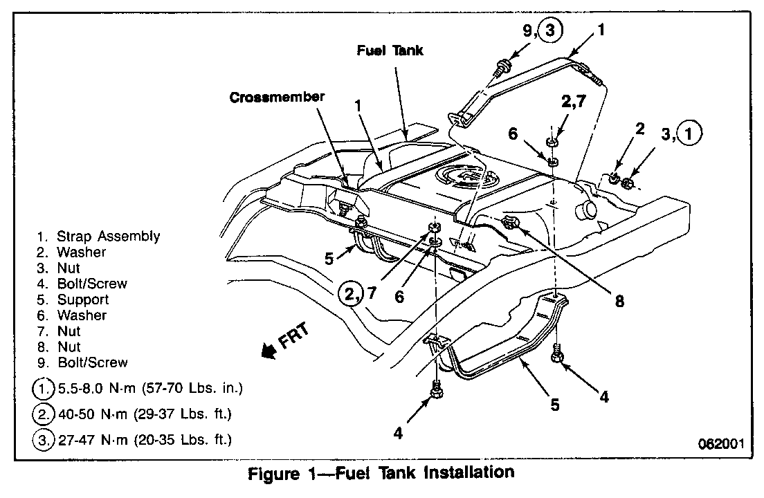
4. Remove fuel tank (Figure 1).
A. Drain fuel from tank through the filler neck using a hand pump or energize in-tank fuel pump and drain from fuel feed line. See service manual for proper procedures and safety precautions.
B. Remove lines and disconnect fuel fill hose and vent hose.
C. Support fuel tank and remove tank supports (5).
D. Lower tank sufficiently to disconnect sender unit connector, fuel lines, and ground terminal.
E. Remove fuel tank.
F. Remove front bolts from tank upper straps and move straps to rear out of the way.
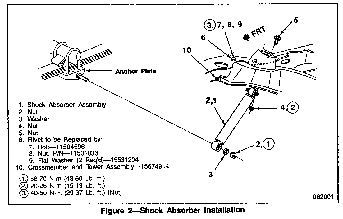
5. Remove shock absorbers (Figure 2).
A. Remove shock absorber to tower bolts and nuts.
B. Remove shock absorber to anchor plate nut and washer.
C. Remove shock absorber from vehicle.
6. Remove rear frame crossmember and towers (Figure 2).
7. Install new frame crossmember and tower assembly (Figure 2).
A. Install three bolts, nuts, and six washers on each side of frame crossmember and torque nuts to 40-51 N-m (29-37 lbs. ft.) or torque bolts to 45-60 N-m (33-44 lbs. ft.).
B. Reinstall shock absorber and torque anchor plate nut to 20-26 N-m (15-19 lbs. ft.).
C. Bolt shock to tower and torque nuts to 58-70 N-m (43-50 lbs. ft.).
8. Reinstall Fuel tank (Figure 1).
A. Raise tank sufficiently to install fuel tank sending unit hoses, electrical connector, and ground strap. Route strap 1 under hoses and wiring.
B. Raise tank fully and install tank supports (5). Torque front strap nuts (9) to 27-47 N-m (20-35 lbs. ft.). Torque support nuts (7) to 40-50 N-m (29-37 lbs. ft.).
C. Reinstall tank shield and torque screws to 9-13 N-m (80-115 lbs. in).
9. Lower vehicle, refill fuel, connect battery negative ground cable.
10. Start engine and check for fuel leaks.
SERVICE PARTS INFORMATION
Part Description Quantity Number -------- ----------------------- --------- 15674914 Rear Frame Crossmember 1 and Shock Tower Assembly
11504596 Bolt, Crossmember Mounting 6
11501033 Nut, Crossmember Mounting 6
15531204 Washer 12
Parts are expected to be available on February 25, 1991. Until then normal part orders will not be accepted by GMSPO. Only verifiable emergency VIP orders will be accepted. GMSPO will make every effort to obtain parts. All parts will be placed on 400 control to waive VIP surcharges. However, the parts will be shipped premium transportation at dealer's expense. All other order types will be canceled as incorrectly ordered while 400 control is in place.
WARRANTY INFORMATION
For vehicles repaired under warranty use: Labor Operation: T7186 Labor Time: 2.5 h rs.
NOTE: Labor Operation is coded to base vehicle coverage in the warranty system.


General Motors bulletins are intended for use by professional technicians, not a "do-it-yourselfer". They are written to inform those technicians of conditions that may occur on some vehicles, or to provide information that could assist in the proper service of a vehicle. Properly trained technicians have the equipment, tools, safety instructions and know-how to do a job properly and safely. If a condition is described, do not assume that the bulletin applies to your vehicle, or that your vehicle will have that condition. See a General Motors dealer servicing your brand of General Motors vehicle for information on whether your vehicle may benefit from the information.
