FRONT PROPELLER SHAFT CV BOOT TORN/CRACKED

SUBJECT: FRONT PROPELLER SHAFT CV BOOT TORN OR CRACKED (INSTALL NEW RETAINING CLAMP)
MODELS: 1991 SYCLONE AND 1992-93 TYPHOON
The front propeller shaft Constant Velocity (CV) boot on some 1991 Syclones and 1992-93 Typhoons may become tom or cracked. This condition may be caused by the retaining clamp "digging" into the rubber boot. If the clamp is too tight, the boot will tend to crack or tear around the edges of the damp.
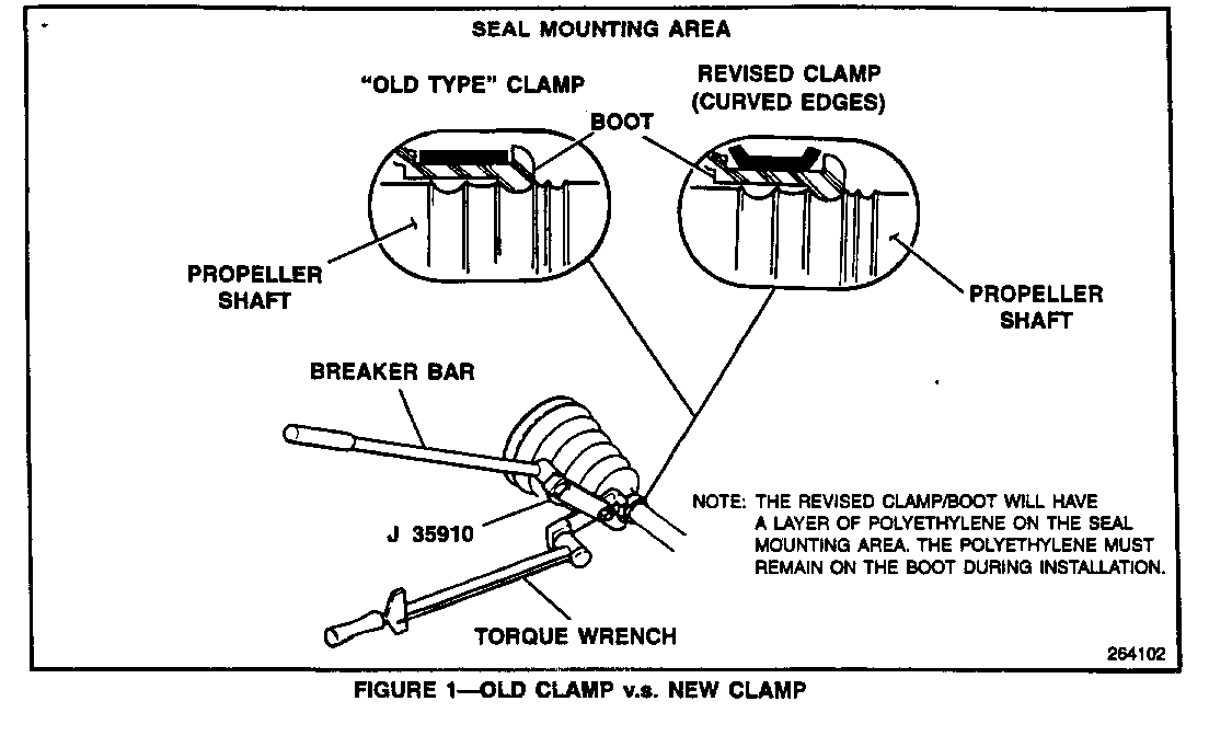
To repair this condition, a new design retaining clamp and a CV boot replacement procedure have been developed. The new retaining clamp has curved edges, as shown in Figure 1. The CV boot also has a strip of polyethylene tape installed on the contact area to prevent the edges of the clamp from digging in.
SERVICE PROCEDURE
1. Remove the front propshaft as detailed in Section 4A of the 1993 Typhoon Service Manual Supplement, X-9376.
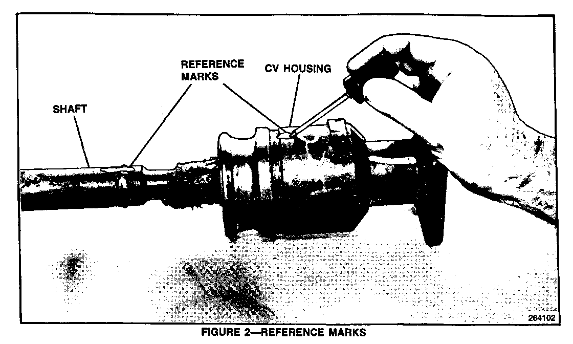
2. Mark the shaft and CV joint housing to maintain proper alignment upon reassembly (Figure 2).
IMPORTANT
It is essential that the positions of all driveline components and propshaft components be observed and reference marked prior to disassembly. All components must be reassembled in the same relationship as they were removed to maintain the factory balance.
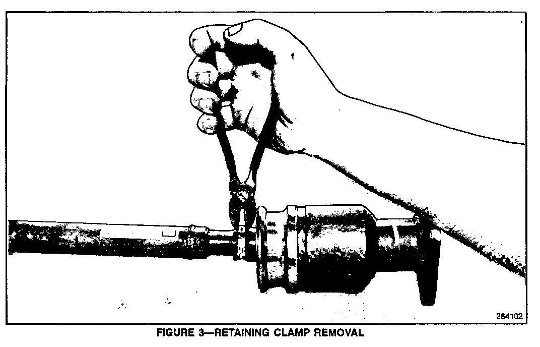
3. Remove the retaining clamp from CV boot as shown in Figure 3.
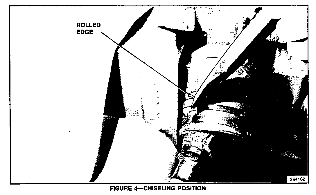
4. Mount the CV joint housing in a vise and peel away the rolled edge of the metal jacket with a chisel. To prevent damage to the CV joint housing DO NOT OVER-TIGHTEN THE VISE (Figure 4).
CAUTION:
To reduce the chance of personal injury, proper eye and face protection should be used when chiseling.
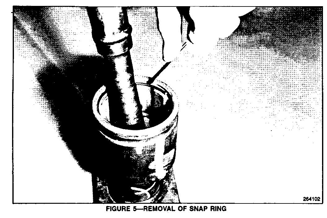
5. Tap the metal jacket off the CV joint housing and slide the CV boot assembly out of the way of the inner CV joint. Wipe away the excess grease inside the CV joint and remove the internal snap ring as shown in Figure 5.
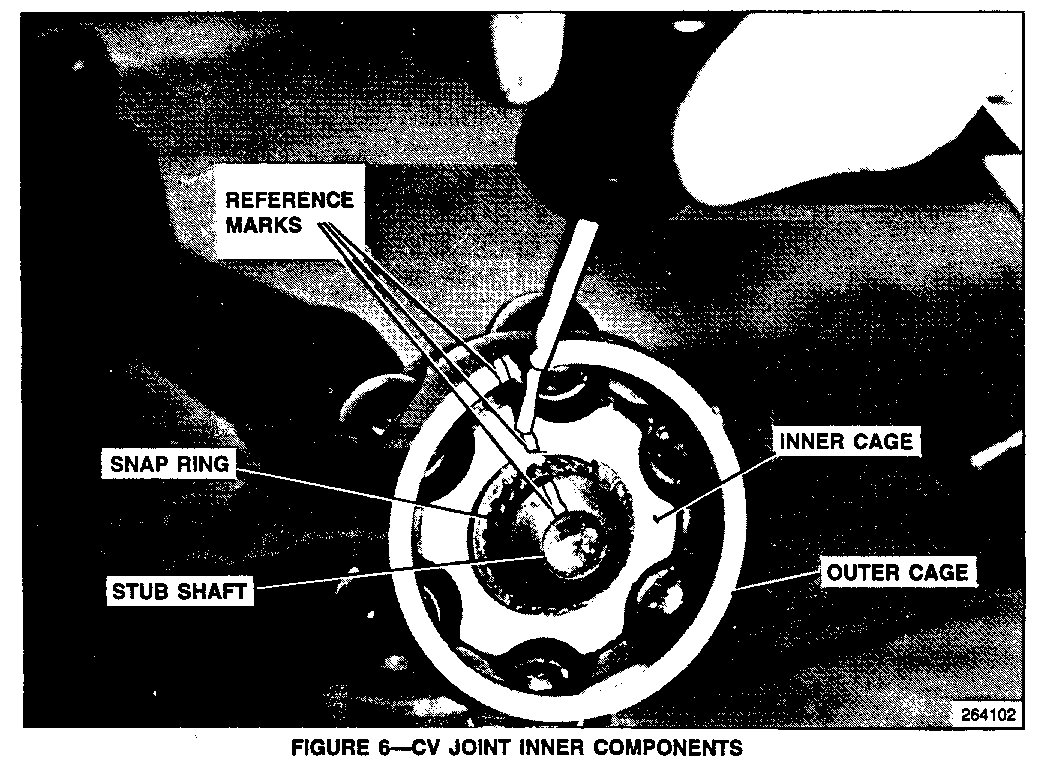
6. Slide the shaft assembly out of the CV joint housing. Clean and completely dry the CV components. Reference mark the stub shaft, and the inner and outer cages to assure proper realignment upon reassembly. Using snap ring pliers, remove the snap ring on the stub shaft and slide the cages off the stub shaft (Figure 6).
NOTE: Inspect all the contact areas internal to the CV joint which include the inner cage, ball bearings and the inner race in the CV joint housing. If signs of excessive wear, chips or damaged components are evident, the propshaft must be replaced.
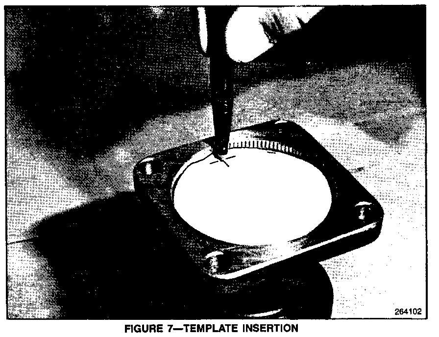
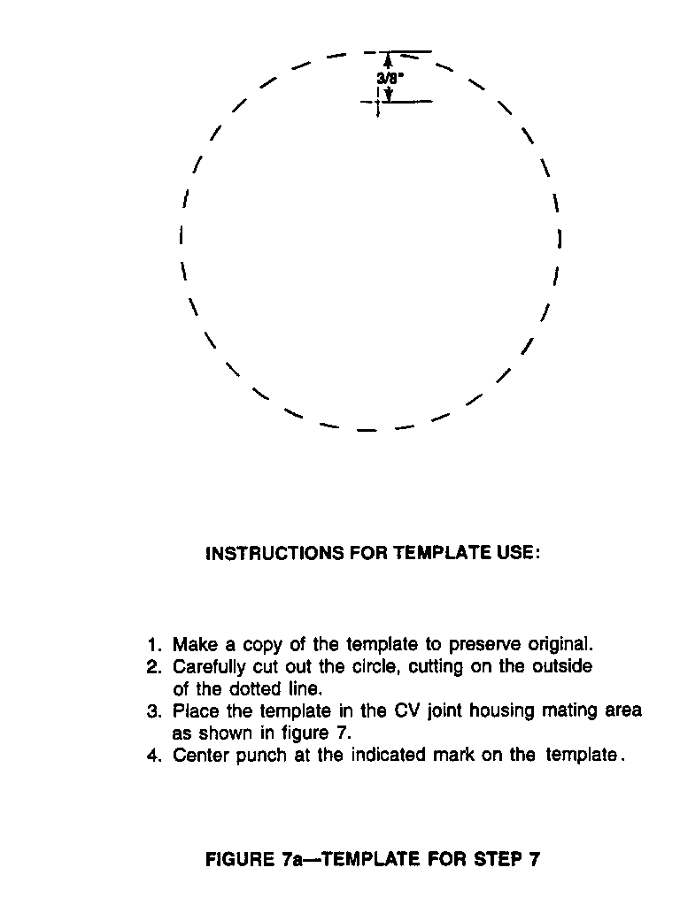
7. Using the template provided (Figure 7A), cut out the template and place it in the CV joint housing mating flange. Center punch at the indicated mark on the template. Drill a 0.136" diameter hole using a #29 drill bit (5/32") through the CV joint flange (Figure 7). This hole will prevent excessive pressure build-up inside the CV joint.
IMPORTANT
Before reassembly, thoroughly clean all parts. Any debris or contamination could cause premature wear.
8. Slide the revised retainer clamp and boot assembly onto the stub shaft.
NOTE: Do not damp the retainer at this time.
9. Aligning the reference marks, install the inner cage, ball bearings, and the outer cage onto the stub shaft. Install the snap ring.
10. Apply about half the contents of the enclosed grease to the inside of the CV joint housing, making sure to coat the inner walls. Keep the center vent hole free from grease.
11. Align the reference marks on the shaft and CV joint housing and insert the shaft assembly into the housing. Install the snap ring on the CV joint housing groove. Pack the remaining grease into the CV joint housing.
12. Apply a very small bead of anaerobic Gasket Maker (P/N 1052842 or 1052943) to the metal jacket mating surface.
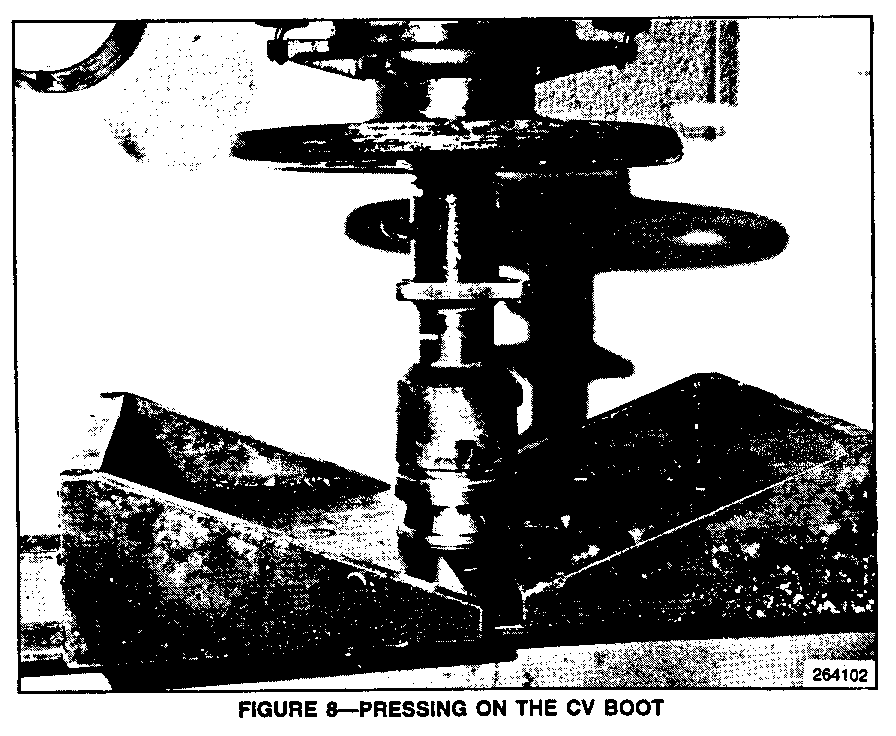
13. By hand, place the CV boot assembly onto the CV joint housing, making sure it is positioned correctly. Place the CV assembly on a vertical press and press the boot assembly onto the housing (Figure 8).
IMPORTANT
Apply only enough pressure to seat the housing evenly into the metal jacket. Too much pressure may damage the CV boot assembly.
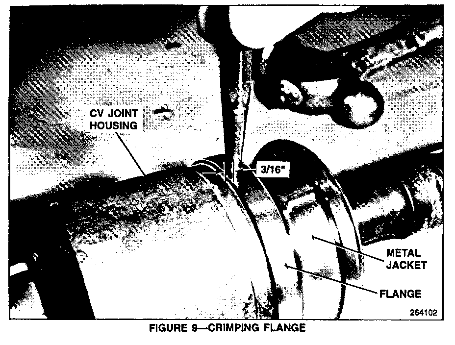
14. Using a center punch, punch 8 evenly-spaced indentations 3/16" from the edge of the metal jacket. This will allow the flange on the metal jacket to "crimp" to the CV joint housing (Figure 9).
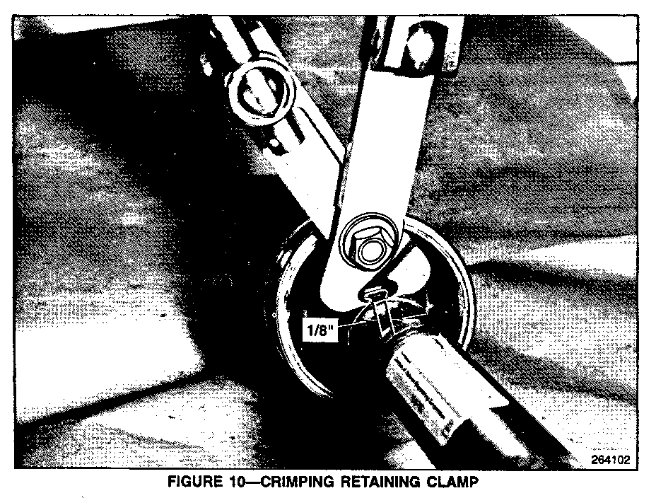
15. Place the boot retaining clamp onto the depressed area on the rubber boot and crimp using a CV boot clamp plier J-35910 or equivalent. When crimping leave a gap of approximately 1/8 (Figure 10).
16. Replace the front propshaft as detailed in Section 4A of the 1993 Typhoon Service Manual Supplement, X-9376.
SERVICE PARTS
Part No. Description Quantity -------- ----------- -------- 12542981 CV Boot Kit for 1991 Syclones with propeller shaft serial 1 number prior to 101208.
12542978 CV Boot Kit for 1991 Syclones with propeller shaft serial 1 number after 101208, and 1992-93 Typhoons.
Note: If there is no serial number found on the propellershaft, measure the outer diameter of the CV housing at the CV boot mating area. If the outer diameter is 81.03 to 80.97 mm, use kit 12542981. If the outer diameter is 80.90 to 80.80 mm, use kit 12542978.
Parts are currently available from GMSPO.
WARRANTY INFORMATION
For vehicles covered under warranty:
Labor Operation: F 1200
Labor Time: 1.0 Hr.
**PLEASE REFER TO FIGURE 7a-TEMPLATE FOR STEP 7 (IMAGE #9) ---------------------------------------------------------- INSTRUCTIONS FOR TEMPLATE USE: ----------------------------- 1. Make a copy of the template to preserve original.
2. Carefully cut out the circle, cutting on the outside of the dotted line.
3. Place the template in the CV joint housing mating area as shown in figure 7.
4. Center punch at the indicated mark on the template.
General Motors bulletins are intended for use by professional technicians, not a "do-it-yourselfer". They are written to inform those technicians of conditions that may occur on some vehicles, or to provide information that could assist in the proper service of a vehicle. Properly trained technicians have the equipment, tools, safety instructions and know-how to do a job properly and safely. If a condition is described, do not assume that the bulletin applies to your vehicle, or that your vehicle will have that condition. See a General Motors dealer servicing your brand of General Motors vehicle for information on whether your vehicle may benefit from the information.
