INSUFFICIENT COOLING FROM A/C SYSTEM- M VANS

MODELS: 1985-1986 M VANS
Complaints may be received on 1985-1986 M vans of insufficient cooling from the air conditioning (A/C) system. The following procedures and modifications can be performed to increase the amount of airflow and cooling from the A/C system. This bulletin is divided into two (2) sections, C60 - Front A/C only and C69 - Front/Rear A/C.
SERVICE PROCEDURES
C60 - FRONT A/C ONLY
The following checks should be made to verify the A/C system is working normally.
1. Verify that the compressor operates normally.
2. Verify correct refrigerant charge - use the insufficient cooling "quick check" procedure on Page 1B-7 of the service manual.
3. System operation - check system operation (performance) test using procedures on Page 1B-7.
4. Temperature Door Adjustment - move the temperature lever rapidly back and forth from hot to cold. Listen for the temperature door hitting the heater case in both modes. A misadjusted temperature door can allow heated air into the A/C air raising the outlet temperature. If the door needs adjusting, use the temperature cable adjustment on Page 1B-32 (86 manual), 1B-17 (85 manual).
If the system checks normal, the following modifications can be used to increase the cooling performance of the A/C system.
5. Add 1/4 lb. of R-12 refrigerant to the system. This will increase the total charge to 1.02 kg (2.25 lbs.). Caution: Use proper safety equipment to prevent personal injury when charging the A/C system.
6. Replace the heater A/C motor with P/N 22021790. This motor operates at higher speed in all ranges. This will increase the air flow into the vehicle. Use procedures on Page 1B-29 (86 manual), 1B-19 (85 manual).
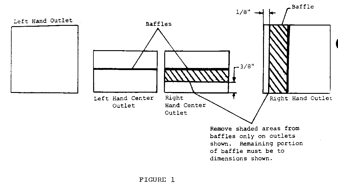
7. Remove right, left, and center A/C outlets. Remove material from right and right center duct baffles (See Figure No. 1).
Inspect the seal that goes between the duct and the right hand outlet. The seal should fit snugly all the way around the duct. Repair if necessary. Similarly, seal the left hand and center ducts to the outlets using foam tape to eliminate all leak paths.
Reinstall the outlets.
8. A vacuum operated "hot water" shut off valve, P/N 14039637, may also be installed to lower the A/C outlet temperature when the A/C is used in the "Max" A/C mode. The addition of the valve will lower the outlet temperature 2 DEG- 3 DEG F. The procedure for installation is as follows:
Installation instructions.
A. Remove the engine cover, air cleaner assembly and the cold air inlet to the air cleaner.
B. Remove plastic conduit from the 5/8" inlet heater hose, see Figure 20 on Page 1A-19 (86 manual).
C. Remove radiator cap.
D. Going as low on the 5/8" inlet heater hose as possible, CUT the hose and install the valve in the hose, securing it by using heater hose clamps. NOTE: The valve must be positioned so that the linkage does not interfere with other components.
E. Locate the A/C vacuum harness under the dash and splice a vacuum TEE into the hose to the recirculation door (BROWN hose). Drill a hole in the cowl and install a vacuum hose 3/32 I.D. (inside diameter) from the vacuum tee to the fitting on the valve. NOTE: The edge of the drilled hole must be protected from corrosion following the procedures for sheet metal repair in section 2C of the service manual. The diameter of the dr il led hole must be as close as possible to the outside diameter of the vacuum hose so that the hose can be sealed to the cowl to prevent water leaks into the truck. Seal the hose to the cowl with weatherstrip adhesive or equivalent.
F. Shorten the plastic conduit as necessary to permit reinstallation and reinstall it on the hose.
G. Refill radiator to proper level and install the radiator cap.
H. Start the vehicle and with the A/C control selector in the bi-level position, check the position of the lever on the shut off valve. Move the A/C lever to "Max" A/C and recheck the position of the lever on the shut off valve. It should have moved to the opposite position on the valve to shut off the water through the heater core.
I. Reinstall the air cleaner, cold air inlet, and the engine cover.
C69 - FRONT AND REAR A/C
Verify that the A/C system is working normally by using the four (4) checks listed in the C60 Section of this bulletin.
If the system checks normal, the following modifications can be used to increase the C69 (front and rear A/C) system performance.
1. Add 3/4 lb. of R-12 refrigerant to the system. This will increase the total charge to 1.69 kg. (3.75 lbs.). This will lower the rear A/C outlet temperature 10 DEG-15 DEG F. Caution: Use proper safety equipment to prevent personal injury when charging the A/C system.
2. Replace the front A/C motor as previously described in the C60 Section, No. 6.
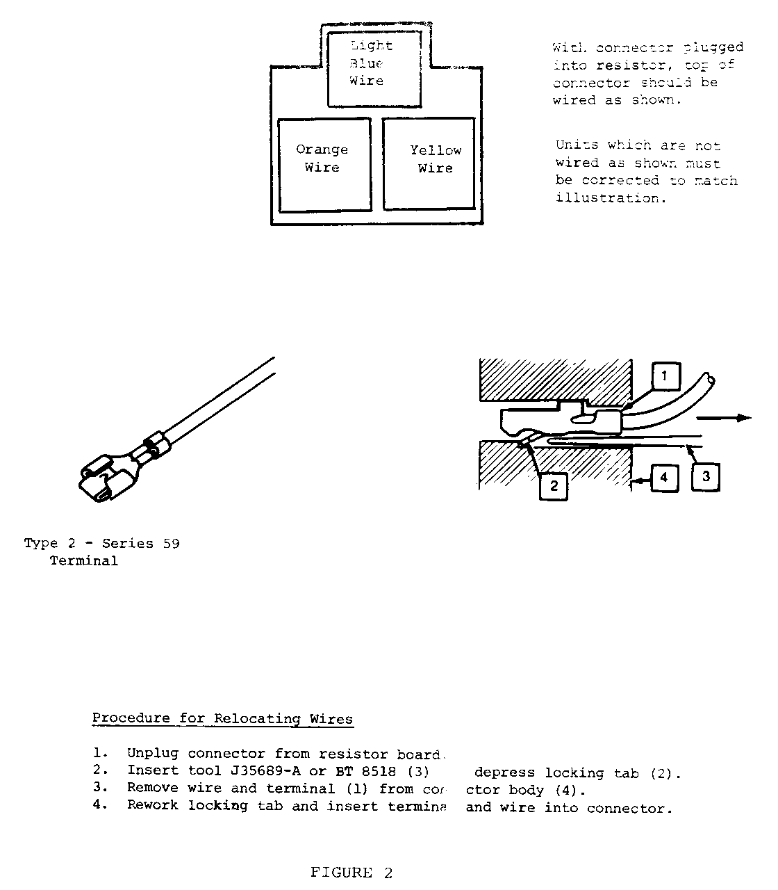
3. Install a new rear A/C motor P/N 22020945 using procedures on Page 1B-35 (86 manual). After installing the motor, the three (3) wire connector on the rear A/C blower motor resistor should be checked for location of the wires in the connector. The wires should be in the positions shown in Figure No. 2. If the wires are in an incorrect position, the yellow and orange wires will have to be switched using procedures in Figure No. 2. An incorrectly positioned wire will result in no blower speed change when changing from low to medium.
4. Check the seal between the side outlet duct and the blower motor housing, Figure 44, Page 1B-37 and correct if necessary to assure a good seal. The front A/C outlet seals should also be checked and baffles modified using the pro- cedure previously described in the C60 Section, No.7.
5. Remove the rear upper outlet duct from the roof using procedures on Page 1B-36 (86 manual).
The roof A/C duct uses the rear section of the headliner as a seal. If the duct does not seal tightly to the headliner, air will leak between the parts. If it becomes necessary to install a seal, foam tape should be used.
The rear edge of the headliner must also be sealed to the body to prevent air from escaping out of the duct and over the headliner. This can be done by sealing the headliner to the body using foam tape.
6. A hot water shut off valve may also be installed using procedures previously described in the C60 Section, No. 8.


General Motors bulletins are intended for use by professional technicians, not a "do-it-yourselfer". They are written to inform those technicians of conditions that may occur on some vehicles, or to provide information that could assist in the proper service of a vehicle. Properly trained technicians have the equipment, tools, safety instructions and know-how to do a job properly and safely. If a condition is described, do not assume that the bulletin applies to your vehicle, or that your vehicle will have that condition. See a General Motors dealer servicing your brand of General Motors vehicle for information on whether your vehicle may benefit from the information.
