AIR CONDITIONING NOISE FRONT AND/OR REAR A/C

VEHICLES AFFECTED: 1990 M AND L VANS WITH FRONT AND/OR REAR AIR CONDITIONING
The 1990 M/L van air conditioning system is new. The new design provides improved air conditioning performance, reliability and quieter compressor operation.
The redesigned system consists of the following new items:
HE6 compressor, with cast accessory drive brackets and new pencil braces. The compressor has been relocated to the LH side of the engine.
Refrigerant hose assemblies have revised routings larger diameter suction hoses and a performed discharge hose and muffler.
The condenser is thicker with openings added to the front body valance panel. Air duct is located below the bumper.
Evaporator assembly is larger.
The heater water control valve shuts off coolant flow to the heater when the temperature selector lever is positioned in full cold.
Isolated attachments for auxiliary A/C system components:
Underbody pipes Auxiliary evaporator module
The 1990 M van A/C system is designed to have a lower noise level than previous M van A/C systems. As in any system, a noise condition can be experienced. If this should occur, it should be determined if it is A/C related.
A/C related noise can be determined by:
Placing the transmission in neutral, blower in off position.
Raising and lowering engine RPM'S.
Moving A/C lever between bi-level and vent. (This will cycle the A/C compressor on and off helping to "tune in" the noise. Make certain compressor does not automatically cycle off).
Noise present in A/C "on" cycle - add Pencil Brace Kit and follow "A/C Noise Diagnostic Chart" (Kit and Chart information found later in Bulletin).
Noise present in A/C "off" cycle - condition is not the fault of the A/C system.
If it is determined to be an A/C related noise, longer pencil braces, Service Kit P/N #10118789, should be added to any 1990 M/L van manufactured prior to the following VIN numbers:
Chevrolet - 1GNDM15Z8LB133267 GMC - 1GDPM1526LB509694
Vehicles built prior to the above VIN numbers are equipped with shorter pencil braces. These should be changed to the longer pencil braces. Brace Kit installation instructions will be provided in the kit. Parts are currently available from CANSPO.
Even with the brace kit installed, a number of other items might cause A/C related noises. To correctly diagnose the specific noise heard, use the "A/C Noise Diagnostic Chart" listed below:
"A/C NOISE DIAGNOSTIC CHART"
NOISE DESCRIPTION SOURCE SOLUTION RECOMMENDATION
Moan or Single Compressor Low RPM -check for groundouts* Frequency Hum. High RPM -check for groundouts* (Occurs at a -Check bolt torques for specific engine loose mounting brackets speed. Reduced -Check for loose or in- or eliminated at correct pencil braces. other engine speeds).
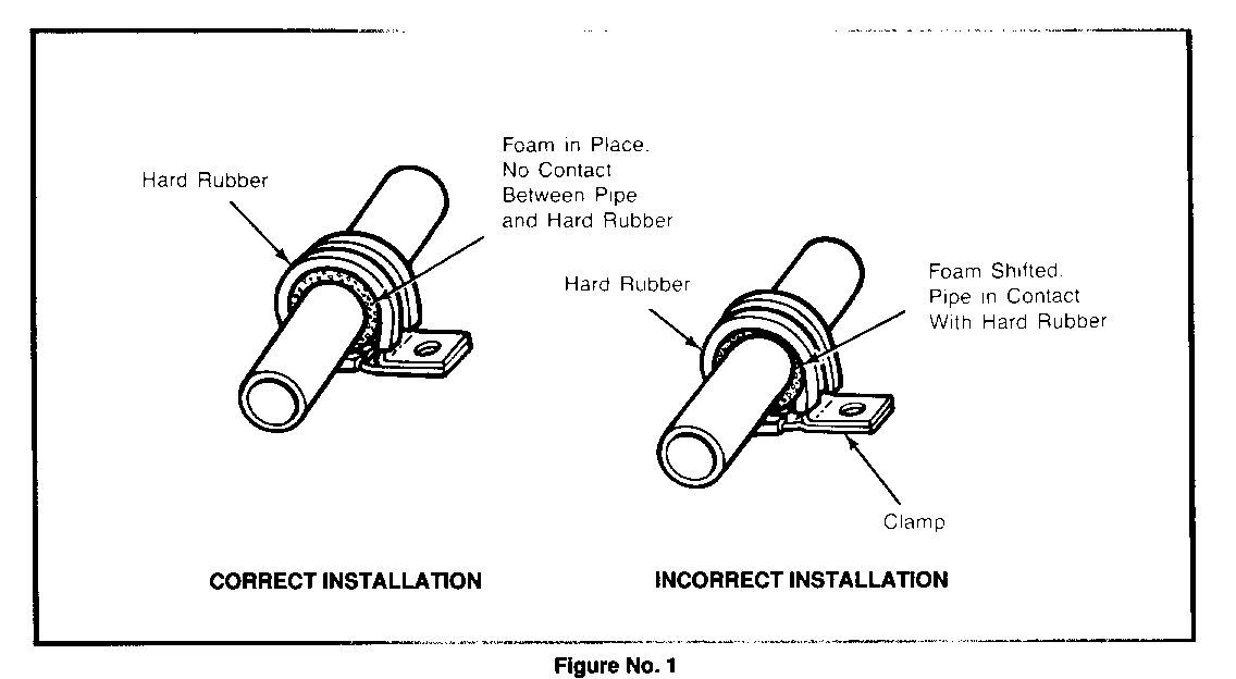
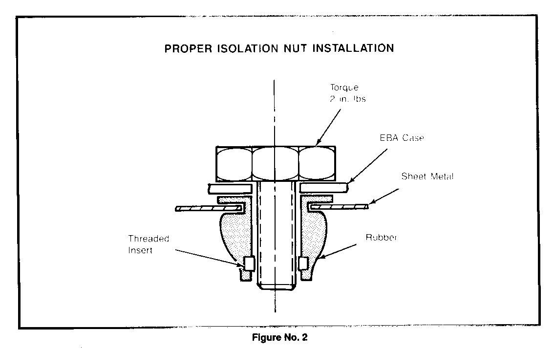
Growl or Machinery Compressor Check for groundouts* on all A/C Noise. (Present lines and components. At all engine speeds. Check for properly isolated Most noticeable clamps on C69 lines underbody at idle). (Refer to Fig. 1). Growl. (Present Compressor Check for groundouts* on all A/C at all engine lines and components. Check for speeds. Most proper installation of rear EBA: noticeable in 3rd Proper installation of rubber seat of C69 equipped isolation nuts. (Refer to Figure 2). Miss, Percolation Thermal Confirm isolation material is or Gurgle Noise. Expansion fastened to trim panel over Comes from left Valve C69 unit properly. corner of C69 (TXV) equipped vans. Most noticeable in 3rd seat).
(*) Groundouts, hard contact between the A/C lines or components and other parts of the van.
Below is a list of possible groundout areas and torques to be checked:
Compressor Suction and Discharqe Hoses: Suction hose or discharge muffler to compressor electrical connector. Suction hose or discharge muffler to compressor body. Discharge hose to rear wheel anti-lock ((RWAL) unit. Discharge hose to brake booster vacuum lines. Condenser inlet pipe to radiator hose clamp. Suction hose to vacuum lines, wire conduit or hood release cable. Suction hose to discharge muffler.
Liquid Lines:
Condenser outlet pipe to radiator inlet tank. Liquid line to radiator overflow nipple. Condenser out liquid line to radiator close out panel. Liquid line "trombone loop" to evaporator case.
C69 System.
Liquid line to C36 water pipes. Liquid line to any part of the body or frame. Liquid line to left hand rear spring hangar bracket. Suction jumper hose to fuel line (left rear of engine). Rear EBA housing to outside sheet metal. Any underbody line to clamp without foam isolation between the line and the clamp strap.
Torques:
Aux.Evaporator Module Attaching Bolts 2 in. lbs. Accessory Drive Bracket to Engine Block 26-40 Nm or 19-30 ft.lbs Accessory Drive Bracket to Compressor 40-60 Nm or 30-44 ft.lbs Pencil Braces to Engine Block 26-40 Nm or 19-30 ft.lbs Pencil Braces to Compressor 20-34 Nm or 15-25 ft.lbs
TXV noise as described in the "Noise Diagnostic Flowchart" will not be improved significantly by adding additional insulation or isolation clips, well nuts or rubber cushions than originally installed by the manufacturer. At this time, alternatives do not exist for improving this condition. TXV or compressor replacement is NOT recommended.
The A/C compressor should NOT be replaced until after the above diagnostic and correction procedure is used and the noise has not been corrected.


General Motors bulletins are intended for use by professional technicians, not a "do-it-yourselfer". They are written to inform those technicians of conditions that may occur on some vehicles, or to provide information that could assist in the proper service of a vehicle. Properly trained technicians have the equipment, tools, safety instructions and know-how to do a job properly and safely. If a condition is described, do not assume that the bulletin applies to your vehicle, or that your vehicle will have that condition. See a General Motors dealer servicing your brand of General Motors vehicle for information on whether your vehicle may benefit from the information.
