Removal Procedure
Tool Required
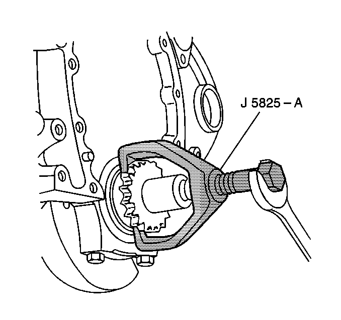
J 5825-A Camshaft Sprocket Puller
- Disconnect the negative battery cable. Refer to
Caution: Unless directed otherwise, the ignition and start switch must be in the OFF or LOCK position, and all electrical loads must be OFF before servicing any electrical component. Disconnect the negative battery cable to prevent an electrical spark should a tool or equipment come in contact with an exposed electrical terminal. Failure to follow these precautions may result in personal injury and/or damage to the vehicle or its components.
in General Information. - Remove the air cleaner assembly and intake duct. Refer to Air Cleaner in Engine Controls.
- Drain the cooling system. Refer to Draining and Refilling the Cooling System in Cooling and Radiator.
- Remove the engine cooling fan. Refer to Fan and Fan Blade Clutch Replacement in Cooling and Radiator.
- Remove the radiator. Refer to Radiator Replacement in Cooling and Radiator.
- Remove the water pump. Refer to Water Pump Replacement in Cooling and Radiator.
- Remove the valve rocker arm covers. Refer to Valve Rocker Arm Cover Replacement (Left Side) or Valve Rocker Arm Cover Replacement (Right Side) .
- Remove the intake manifold. Refer to Intake Manifold Replacement .
- Remove the engine front cover. Refer to Engine Front Cover Replacement .
- Remove the valve lifters and the pushrods. Refer to Valve Lifter Replacement .
- Align the timing marks.
- Remove the camshaft sprocket bolts.
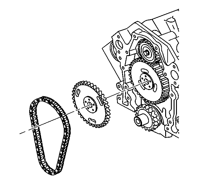
- Remove the camshaft sprocket, the balance shaft drive gear, and the timing chain. The sprocket is a light interference fit on the camshaft. Tap the sprocket on its lower edge to loosen it.
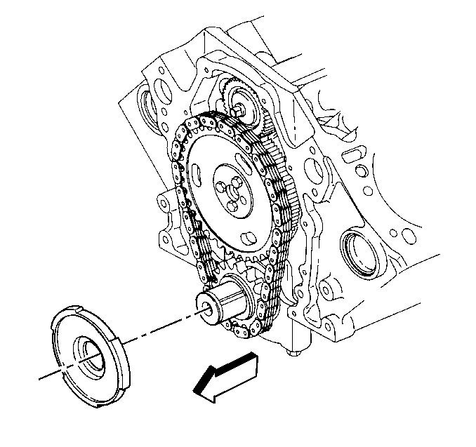
- Remove the crankshaft position sensor reluctor ring.
- Remove the crankshaft sprocket, if necessary. Use the J 5825-A .
- Remove the camshaft.
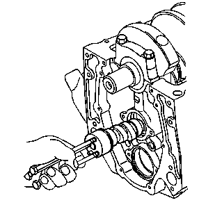
| 16.1. | Install two or three 5/16 18 bolts, 100 to 125 mm (4 to 5 inches) long, into the camshaft threaded holes. Use these bolts to handle the camshaft. |
| 16.2. | Pull the camshaft from the block. |
| 16.3. | Do not damage the camshaft bearings. |
Installation Procedure
Tool Required
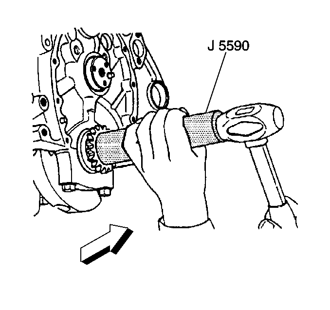
J 5590 Crankshaft Sprocket Installer
- Coat the camshaft lobes and the journals with a high viscosity oil with zinc GM P/N 12345501 or equivalent.
- Install two or three 5/16 18 bolts 100 to 125 mm (4 to 5 in) long into the camshaft threaded holes. Use these bolts to handle the camshaft.
- Install the camshaft in the engine. Handle the camshaft carefully to prevent damage to the camshaft bearings.
- Install the crankshaft sprocket. Use the J 5590 . Make sure the timing mark faces outside.
- Install the balance shaft drive gear, camshaft sprocket and the timing chain. Refer to Balance Shaft Replacement for alignment of the balance shaft drive gear and the driven gear.
- Install the camshaft sprocket bolts.
- Install the crankshaft position sensor reluctor ring.
- Install the valve lifters and the pushrods. Refer to Valve Lifter Replacement .
- Install the intake manifold. Refer to Intake Manifold Replacement .
- Install the distributor. Refer to Distributor Replacement in Ignition System.
- Install the engine front cover. Refer to Engine Front Cover Replacement .
- Install the crankshaft balancer. Refer to Crankshaft Balancer Replacement .
- Install the water pump. Refer to Water Pump Replacement in Cooling and Radiator.
- Install the valve rocker arms covers. Refer to Valve Rocker Arm Cover Replacement (Left Side) or Valve Rocker Arm Cover Replacement (Right Side) .
- Install the engine cooling fan. Refer to Fan and Fan Blade Clutch Replacement in Cooling and Radiator.
- Install the radiator. Refer to Radiator Replacement in Cooling and Radiator.
- Fill the cooling system with the proper quantity and grade of coolant. Refer to Specifications in Cooling and Radiator.
- Install the air cleaner assembly and the intake duct. Refer to Air Cleaner in Engine Controls.
- Connect the negative battery cable.

Important: Line up the timing marks on the camshaft sprocket and the crankshaft sprocket dot to dot. When these dots are lined up dot to dot, the number four cylinder is at the top dead center of its compression stroke. Position the distributor rotor facing the cap hold down mount nearest the flat side of the housing.

Tighten
Tighten the camshaft sprocket bolts to 28 N·m (21 lb ft).
Notice: Use the correct fastener in the correct location. Replacement fasteners must be the correct part number for that application. Fasteners requiring replacement or fasteners requiring the use of thread locking compound or sealant are identified in the service procedure. Do not use paints, lubricants, or corrosion inhibitors on fasteners or fastener joint surfaces unless specified. These coatings affect fastener torque and joint clamping force and may damage the fastener. Use the correct tightening sequence and specifications when installing fasteners in order to avoid damage to parts and systems.

Important: Whenever a new camshaft is installed, do the following procedures:
• Replace all the valve lifters. • Change the engine oil. • Change the oil filter. • Add GM Engine Oil Supplement GM P/N 1052367 or the
equivalent to the engine oil.
