Step
| Action
| Value(s)
| Yes
| No
|
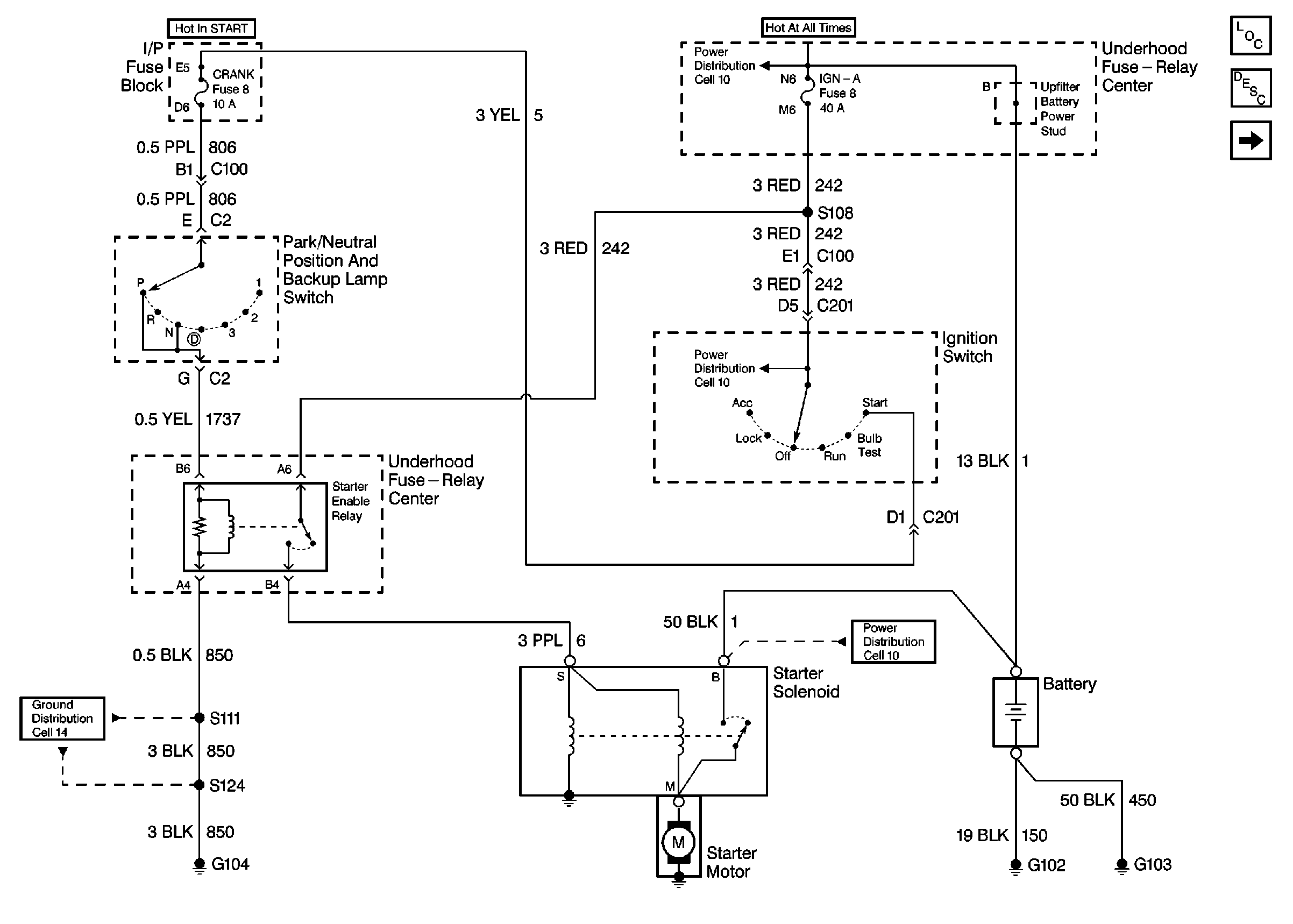
DEFINITION: The engine does not crank (rotate) and the
Starter Solenoid does not click when the Ignition Switch is placed in the
Start position. The battery does display the green dot.
|
1
|
- Remove starter enable relay.
- Connect a voltmeter from starter enable relay connector RED (242)
wire cavity A6 to ground.
- Refer to
Engine Electrical Starter

Did the voltmeter indicate battery voltage?
| --
|
Go to Step 3
|
Go to Step 2
|
2
| Repair open in RED (242) wire from IGN-A maxi fuse at power distribution
center to starter enable relay
Engine Electrical Starter

.
Are the repairs complete?
| --
| Go to
Starter and Charging System Check
.
| --
|
3
| Connect an ohmmeter between the starter enable relay BLK
(850) wire cavity A4 and ground.
Did the ohmmeter indicate continuity?
| --
|
Go to Step 5
|
Go to Step 4
|
4
| Repair the open BLK (850) wire between the starter enable relay and
ground G104.
Are the repairs complete?
| --
| Go to
Starter and Charging System Check
.
| --
|
5
|
- Connect a voltmeter between the starter enable relay YEL (1737)
wire cavity B6 and ground.
- Place the Ignition Switch in the START position.
- Observe the indicated voltage.
- Place the ignition switch in the OFF position.
Did the voltmeter indicate battery voltage?
| --
|
Go to Step 6
|
Go to Step 13
|
6
| Momentarily connect a fused jumper from RED (242) wire cavity A6 to
PPL (6) wire cavity B4 of starter enable relay.
Did the engine crank?
| --
|
Go to Step
7
|
Go to Step 8
|
7
| Replace the starter enable relay.
Are the repairs complete?
| --
| Go to
Starter and Charging System Check
.
| --
|
8
|
| • | Reconnect the starter enable relay. |
| • | Connect a voltmeter from PPL (6) wire cavity S at starter solenoid
to ground. |
| • | Place the ignition switch in the START position. |
Did the voltmeter indicate battery voltage?
| --
|
Go to Step 10
|
Go to Step 9
|
9
| Repair the open PPL (6) wire between the starter enable relay and the
starter solenoid.
Are the repairs complete?
| --
| Go to
Starter and Charging System Check
.
| --
|
10
|
- Connect a voltmeter between the PPL (6) wire cavity S at the
starter solenoid and to the starter motor bolts.
- Place the Ignition Switch in the START position.
- Observe the indicated voltage.
- Place the ignition switch in the OFF position.
Did the voltmeter indicate battery voltage?
| --
|
Go to Step 11
|
Go to Step 12
|
11
| Replace the starter solenoid.
Are the repairs complete?
| --
| Go to
Starter and Charging System Check
.
| --
|
12
| Clean starter motor mounting bolts, starter motor and mounting
surface.
Are the repairs complete?
| --
| Go to
Starter and Charging System Check
.
| --
|
13
|
- Disconnect the Park/Neutral Position and Backup Lamp Switch C2
connector.
- Connect a voltmeter between the PPL (806) wire cavity E at the
switch connector to ground.
- Place the Ignition Switch in the START position.
Did the voltmeter indicate battery voltage?
| --
|
Go to Step 14
|
Go to Step 17
|
14
|
- Connect a fused jumper from PPL (806) wire cavity E at the park/neutral
position and backup lamp switch C2 connector to YEL (1737) wire.
- Place the ignition switch in the START position.
Did the engine crank?
| --
|
Go to Step 15
|
Go to Step 16
|
15
| Replace the park/neutral position and backup lamp switch.
Are the repairs complete?
| --
| Go
to
Starter and Charging System Check
.
| --
|
16
| Locate and repair
open in YEL (1737) wire between park/neutral position and backup lamp switch
and underhood fuse-relay center
Are the repairs complete?
| --
| Go
to
Starter and Charging System Check
.
| --
|
17
|
- Using a voltmeter backprobe YEL (5) wire cavity D1 at C201 connector
to ground
- Place the ignition switch in the START position.
Did the voltmeter indicate battery voltage?
| --
|
Go to Step 18
|
Go to Step 19
|
18
| Using a voltmeter backprobe RED (242) wire
cavity D5 at C201 connector to ground
Did the voltmeter indicate battery voltage?
| --
| Go to
Starter and Charging System Check
.
| --
|
19
| Using a voltmeter backprobe RED (242) wire cavity D5 at C201 connector to
ground
Did the voltmeter indicate battery voltage?
| --
|
Go to Step 20
|
Go to Step 21
|
20
| Replace the ignition switch
Are the repairs complete?
| --
| Go
to
Starter and Charging System Check
.
| --
|
21
| Locate and repair
open in RED (242) wire between ignition switch and underhood fuse-relay
center
Are the repairs complete?
| --
| Go
to
Starter and Charging System Check
.
| --
|

