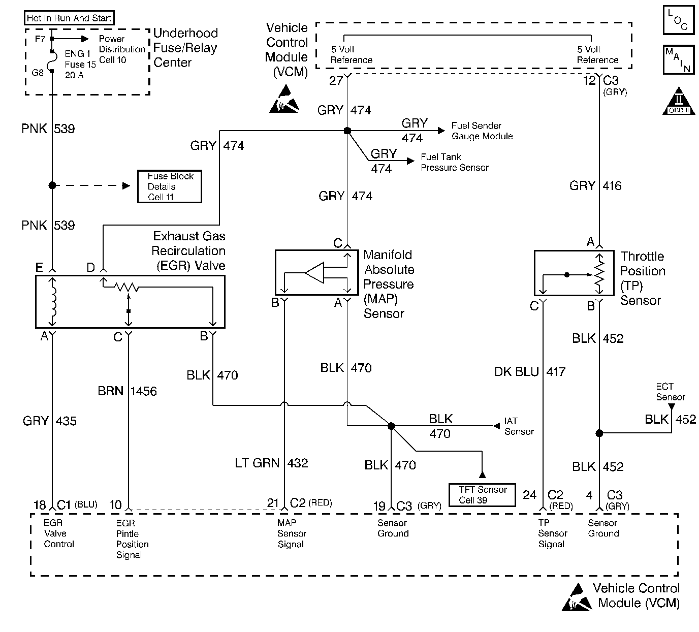
Circuit Description
The Throttle Position (TP) sensor provides a voltage signal that changes relative to the throttle opening. The TP sensor signal voltage varies from about 0.6 volts at idle to about 4.8 volts at Wide Open Throttle (WOT).
The TP sensor signal is one of the most important inputs used by the VCM for fuel control and for most of the VCM control inputs. This DTC is a type B DTC.
Conditions for Setting the DTC
| • | No MAP DTCs are present. |
| • | No TP DTCs are present. |
| • | No IAC DTCs are present. |
| • | Engine is running. |
| • | BARO is not at calculated default. |
| • | Change in TP is less than 1.9%. |
Stuck High Test
| • | MAP less than 50 kPa. |
| • | The last throttle position value is greater than the predicted throttle position based on engine RPM. |
Stuck Low Test
| • | Stuck High Test has passed. |
| • | MAP greater than 60 kPa. |
| • | IAC greater than 10 counts but less than 340 counts. |
| • | The last throttle position value is less than the predicted throttle position based on engine RPM. |
Action Taken When the DTC Sets
The VCM turns ON the MIL after 2 consecutive driving cycles with the fault active. The TP sensor reads 0% if the vehicle speed is less than 2 mph. The TP sensor reads 10% if the vehicle speed is greater than 2 mp/h. The scan tool will show a defaulted value.
Conditions for Clearing the MIL/DTC
The VCM turns OFF the MIL after 3 consecutive driving trips without a fault condition present. A history DTC will clear if no fault conditions have been detected for 40 warm-up cycles (the coolant temperature has risen 22°C (40°F) from the start-up coolant temperature and the engine coolant temperature exceeds 71°C (160°F) during that same ignition cycle) or the scan tool clearing feature has been used.
Diagnostic Aids
The scan tool displays the throttle position in volts. It should display from 0.20 volts to 0.90 volts with the throttle closed and the ignition ON or at idle. The voltage should increase at a steady rate as the throttle is moved toward Wide Open Throttle (WOT). Also, the scan tool displays the throttle angle %. 0% = closed throttle. 100% = WOT.
Check the condition of the connector and the sensor terminals for moisture or corrosion. Clean the connector and the sensor terminals for moisture or corrosion. Replace the connector and the sensor terminals for moisture or corrosion as necessary. If corrosion is found, check the condition of the connector seal and repair or replace the connector seal if necessary. If DTC P0121 is intermittent, refer to the Driveability Symptom Tables.
Test Description
The numbers below refer to the step numbers on the diagnostic table.
-
The TP sensor has an auto zeroing feature. If the voltage reading is within the range of about 0.2 to 0.9 volt, the VCM uses that value as a closed throttle. If the reading is out of the auto zero range at the closed throttle, check for a binding throttle or a damaged linkage. If the throttle and the linkage are okay, continue with the diagnosis.
-
With the TP sensor disconnected, the TP sensor voltage should go low if the VCM and the wiring are okay.
Step | Action | Value(s) | Yes | No |
|---|---|---|---|---|
1 |
Important: Before clearing the DTCs, use the scan tool in order to record the Freeze Frame and the Failure Records data. Using the Clear Info function will lose this data. Was the Powertrain On-Board Diagnostic (OBD) System Check performed? | -- | ||
Does the scan tool display the TP sensor percentage above the specified value? | 2% | |||
3 |
Does the scan tool display the TP sensor percentage above the specified value? | 0%-99.6% 2% | ||
Disconnect the TP sensor electrical connector. Does the scan tool display the TP sensor at the specified value? | 0.00V | |||
5 | The DTC is intermittent. If no additional DTCs are stored, refer to the Diagnostic Aids. If additional DTCs are stored refer to those tables first. Were additional DTCs stored? | -- | Go to The Applicable DTC Table | |
6 | Check for a faulty connections at the TP sensor. Was a problem found? | -- | ||
7 | Repair the circuit as necessary. Refer to Wiring Repairs in Engine Electrical. Is the action complete? | -- | -- | |
8 | Replace the TP sensor. Refer to TP Sensor Replacement . Is the action complete? | -- | -- | |
9 | Replace the VCM. Important: If the VCM is faulty, program the new VCM. Refer to VCM Replacement/Programming . Is the action complete? | -- | -- | |
10 |
Does the scan tool indicate that this diagnostic ran and passed? | -- | ||
11 | Using the scan tool, select the Capture Info and the Review Info. Are any DTCs displayed that have not been diagnosed? | -- | Go to The Applicable DTC Table | System OK |
