For 1990-2009 cars only
Removal Procedure
Tools Required
J 36202 Torsion Bar Unloading/Loading Tool
- Raise the vehicle. Refer to Lifting and Jacking the Vehicle in General Information.
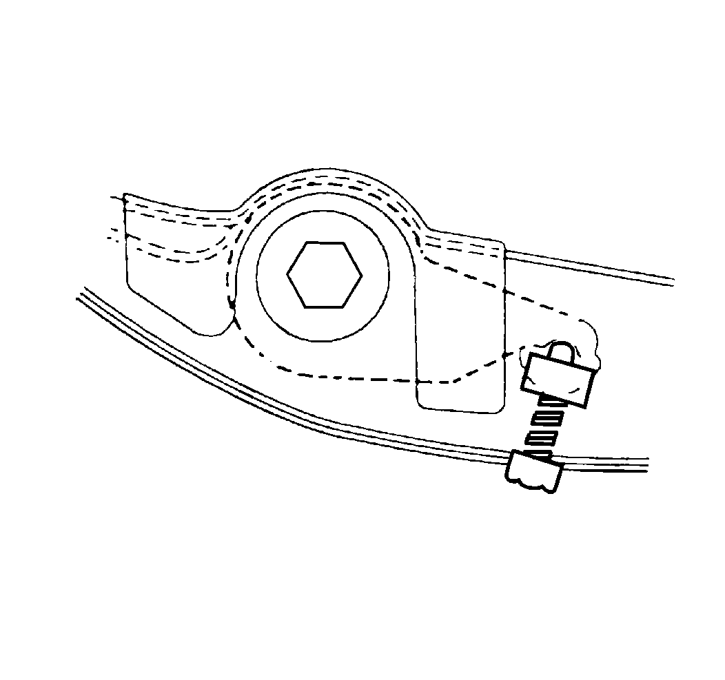
- Remove the adjustment assemblies on the torsion bar. Mark the adjustment bolt setting.
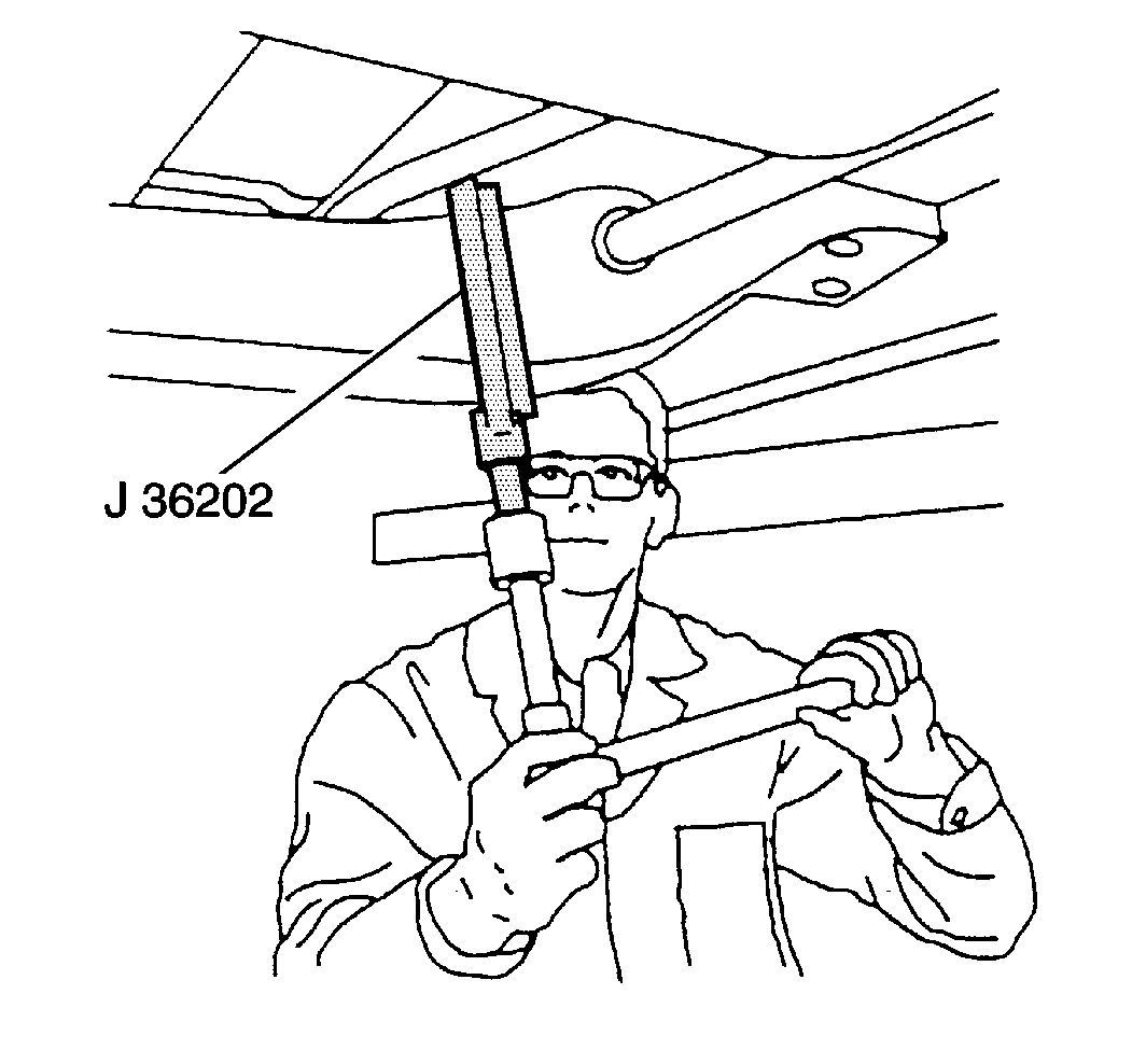
- Using the J 36202 , increase the tension on the adjustment arm.
- Remove the adjustment bolt and the retaining nut.
- Move the tool aside.
- Remove the torsion bar adjustment arm.
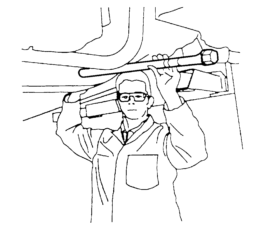
- Slide the torsion bar back partially through the crossmember.
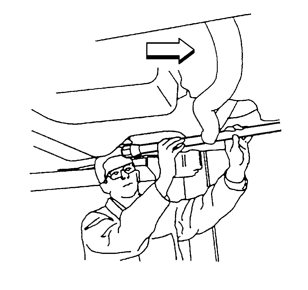
- Drop the front end of the torsion bar down and slide the bar forward. Note the L for left and the R for right on the front end of the torsion bar because there are different bars for the left and right sides.
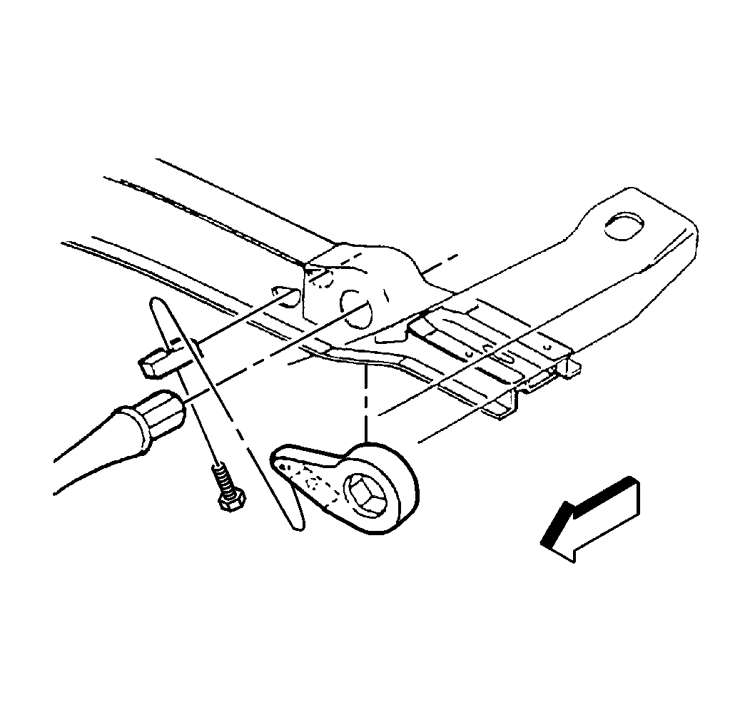
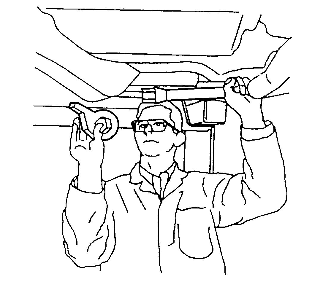
| 6.1. | Slide the torsion bar forward. |
| 6.2. | Remove the adjustment arm. |
Installation Procedure
- Install the torsion bar. Note the L for left or R for right on the front end of the torsion bar because there are different bars for the left and right sides.
- Lubricate the adjuster assembly with axle with axle grease on the adjuster arm and the bolt.
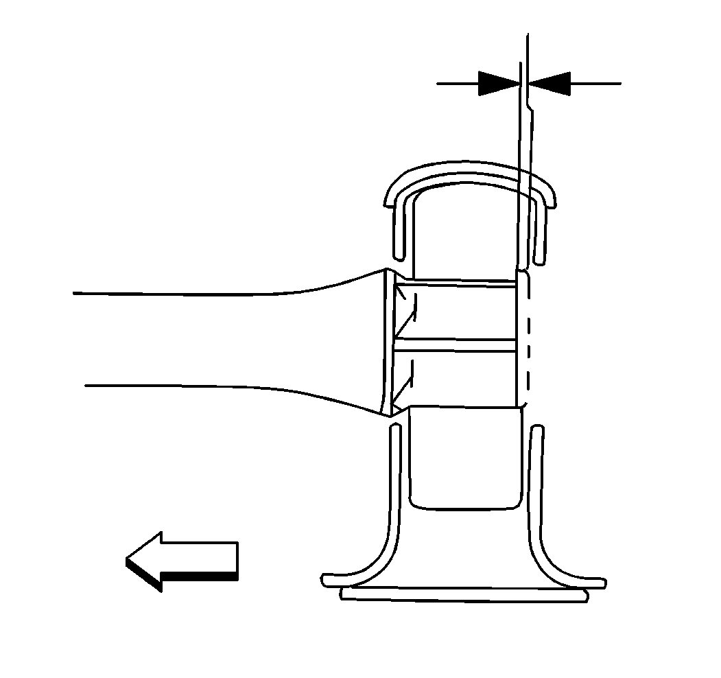
- Install the torsion bar adjuster arm. The rear face of the torsion bar should be within 1.0-2.0 mm (0.04-0.10 in) of the rear face of the adjuster arm when both are fully installed.
- Install the adjustment retaining nut and the adjustment bolt. Using the J 36202 , increase the tension on the torsion bar.
- Install the retaining nut and the adjustment bolt.
- Set the adjustment bolt to the marked setting.
- Using the J 36202 , release the tension on the torsion bar until the load is taken up by the adjustment bolt.
- Remove the J 36202 .
- Lower the vehicle.
- Check the Z height. Refer to Trim Height in Suspension General Diagnosis.


