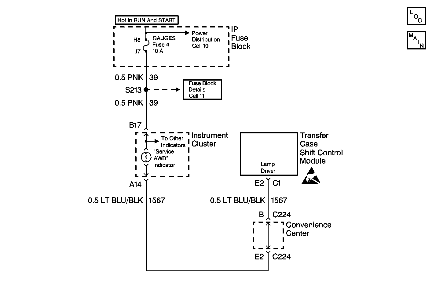
Circuit Description
The Transfer Case Shift Control Module controls the SERVICE indicator (AWD/4WD) lamp, located in the Instrument Cluster, by grounding circuit 1567. Voltage to the lamp is supplied via the Gauge Fuse, circuit 39. The fuse is located in the I/P Fuse Block.
Conditions for Setting the DTC
After the Transfer Case Shift Control Module commands the lamp on, the module senses a voltage greater than 7 V on circuit 1567.
Conditions for Clearing the DTC
| • | The Transfer Case Shift Control Module will clear the DTC if the condition for setting the DTC no longer exists. |
| • | A history DTC will clear after 100 consecutive ignition cycles without a fault present. |
| • | Use a scan tool in order to clear history DTCs. |
Test Description
The number(s) below refer to the step number(s) on the diagnostic table.
-
This step determines whether circuit 1567 is shorted to voltage.
-
Jumping terminal E2 of the transfer case shift control module harness connector to ground should provide a complete path to ground for the Service 4WD lamp. This step attempts to eliminate the instrument cluster and wiring from fault.
Step | Action | Value(s) | Yes | No |
|---|---|---|---|---|
1 | Was the Transfer Case Diagnostic System Check performed? | -- | Go to Step 2 | |
2 |
Are the terminals damaged or corroded? | -- | Go to Step 5 | Go to Step 3 |
Is the voltage reading greater than the specified voltage? | 0 V | Go to Step 4 | Go to Step 6 | |
4 | Repair a short to voltage in CKT 1567. Refer to Wiring Repairs in Wiring Systems. Is the repair complete? | -- | Go to Step 11 | -- |
5 | Repair the instrument cluster wire harness connector. Refer to Wiring Repairs in Wiring Systems. Is the repair complete? | -- | Go to Step 11 | -- |
Does the Service 4WD lamp light? | -- | Go to Step 7 | Go to Step 8 | |
7 | Replace the transfer case shift control module. Refer to Transfer Case Shift Control Module Replacement. Is the action complete? | -- | Go to Step 11 | -- |
8 | Inspect instrument cluster Service 4WD lamp for faulty bulb. Is the bulb good? | -- | Go to Step 10 | Go to Step 9 |
9 | Replace instrument cluster SERVICE 4WD bulb. Refer to Instrument Cluster Bulb Replacement . Is the repair complete? | -- | Go to Step 11 | -- |
10 | Remove instrument cluster for service. Refer to Instrument Cluster Replacement . Is the repair complete? | -- | Go to Step 11 | -- |
11 |
Have all the ATC components been reconnected and properly mounted? | -- | Go to Step 12 | -- |
12 | Clear all ATC DTCs. Have all the ATC DTCs been cleared? | -- | -- |
