The power door locks are operated by reversible motors. The motors are found in the following locations:
| • | In each front door |
| • | The side door |
| • | The rear door |
The PWR ACCY circuit breaker (30A) supplies voltage to the door lock motors.
If you move either power door lock switch, mounted in the front doors, the LOCK applies voltage to cavity F of the door lock relay. This energizes the lock coil in the relay. Current then flows through CKT 295 (GRY) directly to the following components:
| • | Both front door lock motors |
| • | The side door lock motor |
| • | The rear door lock motor (cargo doors only) |
CKT 246/294 (TAN) provides the ground for the motors. The normally closed contacts of the UNLOCK then contacts the door lock relay.
If you move one of the door lock switches to UNLOCK the polarity of the system reverses. Current flows through the energized UNLOCK relay contacts. The LOCK relay contacts provide ground.
When the UNLOCK button is pressed once on the RKE transmitter, only the driver door unlocks. If it is pressed a second time within 5 seconds, all doors unlock.
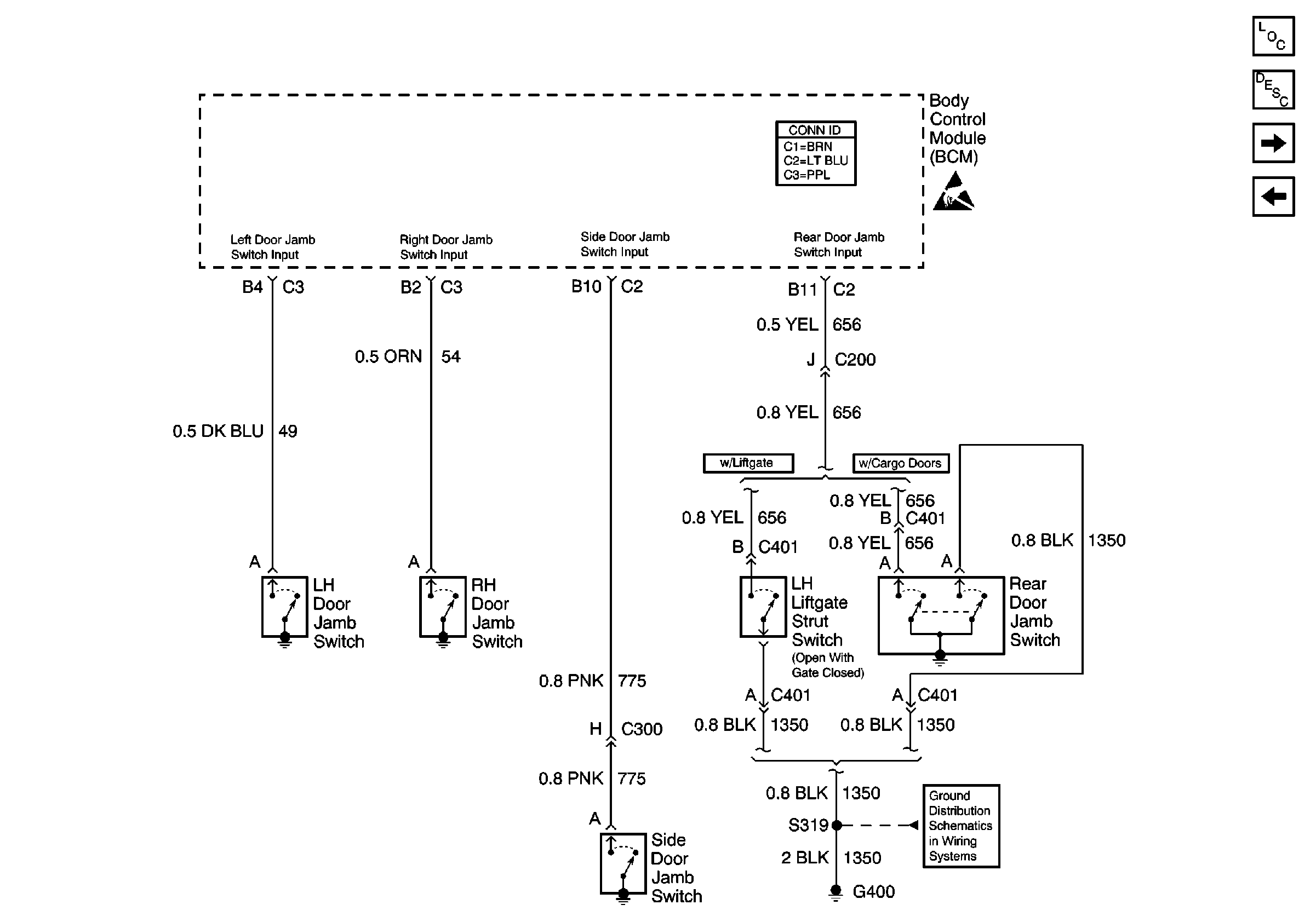
If the side door is open, the side door jamb switch ground signal is opened/broken. If you move the door lock switch to LOCK while the side door is open, the following actions occur:
| • | The 2 front doors lock |
| • | The rear door locks (cargo doors only) |
When you close the side door, the door jamb switch closes. This closes
the ground signal to the body control module {CKT 775 (PNK)}. A 5 second
timer then starts in the module. After 5 seconds, cavity A4 connector C1
of the body control module supplies voltage to the door lock relay via
CKT 195 (LT BLU). This energizes the door lock relay, which
sends voltage to the door lock motors in order to lock the side door. Refer
to
Door Jamb Switches, Liftgate Strut Switch

for a schematic of
all door jamb switch inputs.
If the side door opens during this 5 seconds, the 5 seconds timer is reset. The locking pulse takes place at the end of the 5 seconds. Unlocking the door resets the 5 second timer in the body control module.
Use the following components in order to unlock the door lock system:
| • | The LH power door lock switch |
| • | The RH power door lock switch |
On vehicles equipped with cargo doors, the cargo door opener mechanically opens the door once the door lock system is unlocked. On vehicle equipped with a liftgate, the liftgate lock/unlock release switch (mechanical key) is added in order to serve the same function as the front power door lock switches. These functions locking and unlocking all doors, including the liftgate. Once the door lock system is unlocked, press the liftgate release switch in order to electrically open the liftgate and pull the handle in order to open the secondary latch.
