Removal Procedure
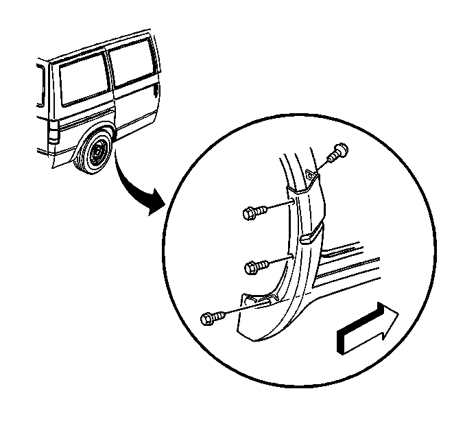
- Remove the screws from the front edge of the assist step extension. Open the door to expose the inner screw.
- Remove the push clips from the front edge of the assist step extension.
- Raise the vehicle to a suitable height.
- Remove the nut from the front lower corner of the assist step extension.
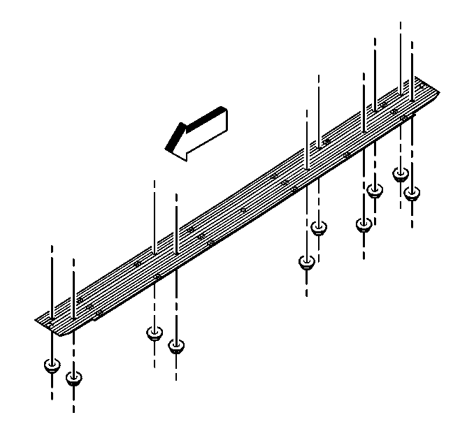
- Remove the assist step pad nuts.
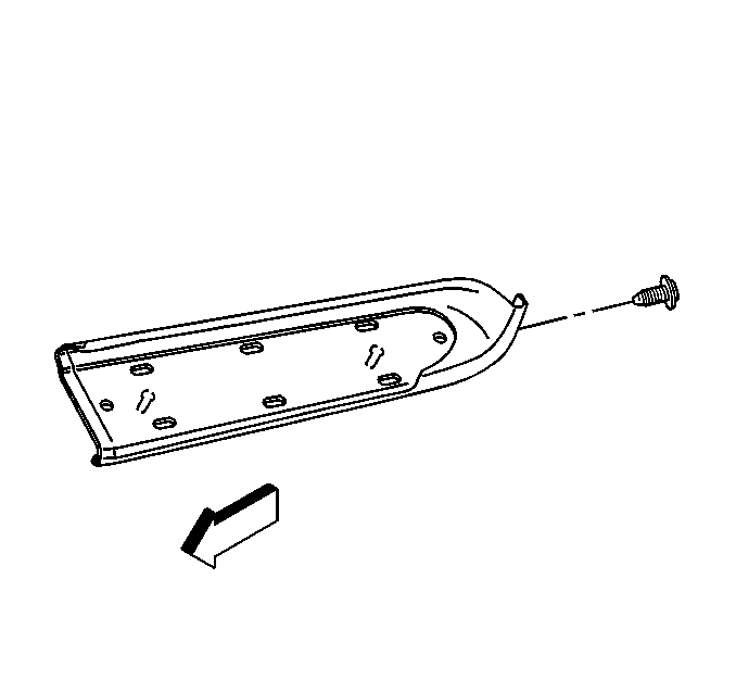
- Remove the assist step pad.
- Remove the front section of the assist step extension as follows:
- Remove the screws from the right rear inner and outer wheel well. Open the sliding door to expose the inner screw.
- Remove the screws from the rear outer edge of the assist step extension. If the vehicle is equipped with assist steps, the cladding is shorter on the left side (bottom edge).
- Remove the rear section of the assist step extension, by lifting upward until fully released from the retainer.
- Remove the nuts that attach the assist step plate to the assist step support bracket .
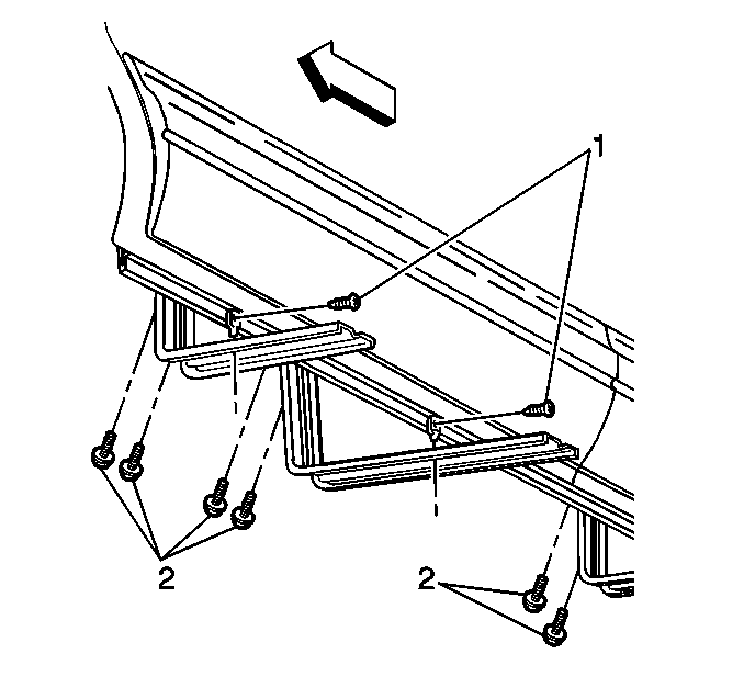
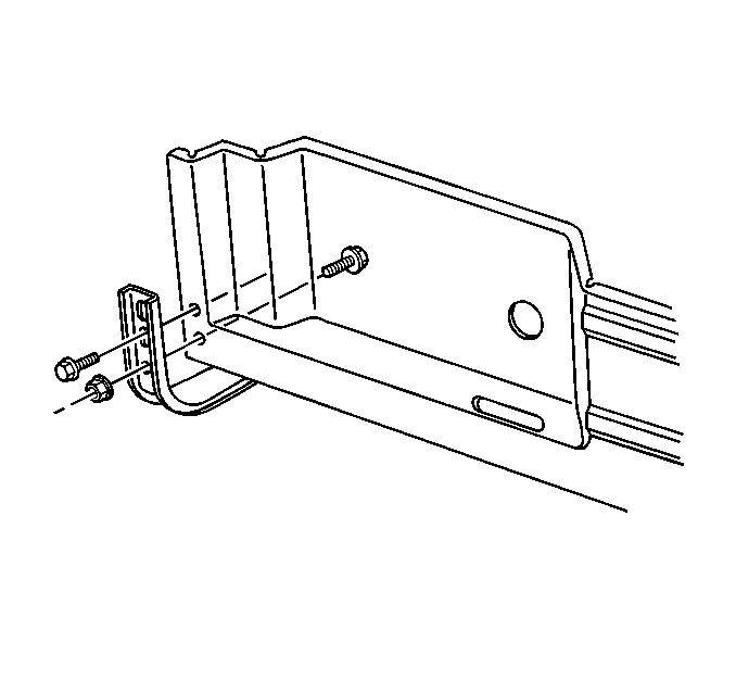
- Remove the bolt (1) from the assist step support brace.
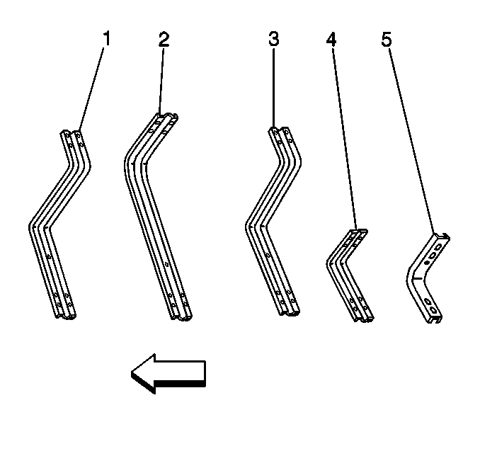
- The assist step support brackets are to be numbered (1, 2, 3, 4, 5) when removing.
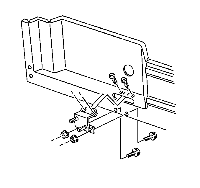
- Remove the bolts (2) from the underbody.
- Remove the assist step support bracket .
- Remove the nuts and bolts from the rear assist step support bracket.
- Remove the rear assist step support bracket.
- Remove the nuts and bolts from the rear anchor that attaches to the inner pinchwell flange and to the inner rocker panel.
- Remove the screws from the assist step retainer. The right side is a one piece retainer, the left side is a two piece retainer.
- Remove the assist step retainer from the rocker panel.
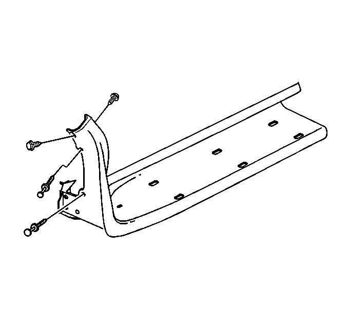
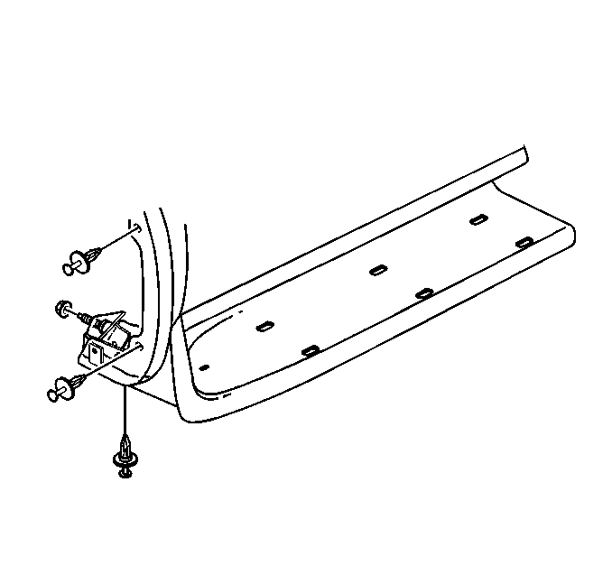
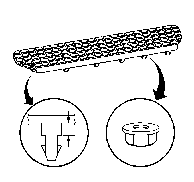
| 6.1. | Insert a plastic tool along the edge. |
| 6.2. | Pull upward on the assist step pad until it is fully released from the assist step plate. |
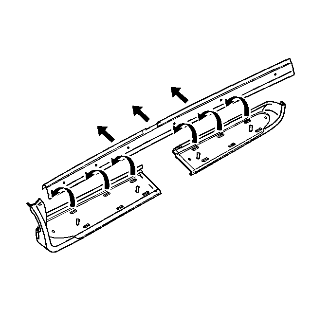
| 7.1. | Lift in the center of the assist step extension. |
| 7.2. | Slide the front section forward. |
| 7.3. | Lift upward on the assist step extension to release it from the retainer and assist plate. |


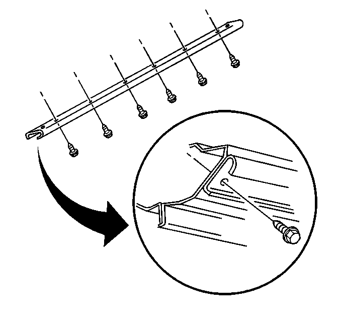
Important: Do not use a sharp tool in the removal of the assist step retainer, it will damage the paint. Use a plastic tool to assist in the removal of the assist step retainer. The assist step retainer is held in place by a double backing tape.
Installation Procedure
- Install the assist step retainer to the rocker panel.
- Install the screws to the assist step retainer.
- Install the nuts and bolts to the rear anchor that attaches to the inner pinchwell flange and to the inner rocker panel.
- Install the rear assist step support bracket.
- Install the nuts and bolts to the rear assist step support bracket.
- Lay out the assist step support brackets in the order in which they were removed (1, 2, 3, 4, 5).
- Install the assist step support brackets and bolts (2) to the underbody.
- Install the bolt from the inside of the pinchweld flange.
- Install the assist step support brace bolt (1) to the pinchweld flange.
- Install the nuts that attach the assist step plate to the support bracket .
- When installing the assist step, check the height and the alignment to rocker panel, cladding and to the body.
- Install the rear section of the assist step extension.
- Install the screws to the rear outer edge of the assist step extension. If the vehicle is equipped with running boards, the cladding will be shorter on the left side only.
- Install the screws to the right rear inner and outer wheel well. Open the sliding door to expose the inner screw.
- Install the assist step extensions to the retainer.
- Install the nut to the front lower corner of the assist step extension.
- Lower the vehicle to a suitable height.
- Install the screws to the front assist step extension. Open the door to expose the inner screw.
- Install the push clips to the front edge of the assist step extension.
- Install the screws to the front edge of the assist step extension.
- Install the assist step pad.
- Align the assist step pad to the assist step plate and press downward firmly until fully seated. The nuts are to be hand torqued.
- Install the assist step pad nuts.
- Lower the vehicle.

The right side is a one piece retainer, the left side is a two piece retainer.
| 1.1. | Clean the rocker panel with isopropyl cleaner or equivalent to remove all of the old double backing tape. |
| 1.2. | Remove the strip from the double back tape if replacing retainer. |
| 1.3. | Align the assist step retainer to the holes in the rocker panel and press in place. |
Notice: Use the correct fastener in the correct location. Replacement fasteners must be the correct part number for that application. Fasteners requiring replacement or fasteners requiring the use of thread locking compound or sealant are identified in the service procedure. Do not use paints, lubricants, or corrosion inhibitors on fasteners or fastener joint surfaces unless specified. These coatings affect fastener torque and joint clamping force and may damage the fastener. Use the correct tightening sequence and specifications when installing fasteners in order to avoid damage to parts and systems.
Tighten
Tighten the screws to the assist step retainer to 2 N·m
(18 lb in).

Tighten
Tighten the nuts and bolts to the rear anchor that attaches to the inner
pinchwell flange and to the inner rocker panel to 25 N·m (18 lb ft).

Tighten
Tighten the nuts and bolts to rear assist step support bracket to 25 N·m
(18 lb ft).


Tighten
Tighten the assist step support bracket and bolts (2)
to the underbody to 25 N·m (18 lb ft).
Tighten
Tighten the assist step support brace bolt (1) to the pinchweld flange
to 10 N·m (89 lb in).

Tighten
Tighten the nuts that attach the assist step plate to the support bracket
to 10 N·m (89 lb in).

Align the rear edge of assist step extension with the rear edge of the retainer and pushing downward until fully seated.

Tighten
Tighten the screws to the rear outer edge of the assist step extension
to 2 N·m (18 lb in).

Tighten
Tighten the screws to the right rear inner and outer wheel well to 2 N·m
(18 lb in).

Important: Use the following steps when installing the assist step extensions to
the retainer:
• Check to ensure that the front assist step extension fits over the
center of the rear extension. • Check for a suitable fit to the step well and the door opening. • Check the height and the alignment to the rocker panel and to the
door opening. • Check the alignment to the cladding and to the body. • Check the alignment gaps between the wheel well molding and body. • Check the lower edge of the assist step extensions to ensure an even
gap along the lower edge of the body.
Tighten
Tighten the nut to the front lower corner of the assist step extension
to 10 N·m (89 lb in).
Tighten
Tighten the front assist step extension screws to 2 N·m
(18 lb in).


Tighten
Tighten the screws to the front edge of the assist step extension to
7 N·m (62 lb in).

Tighten
Tighten the assist step pad nuts to 2 N·m (18 lb in).
