Product Safety - Multifunction Switch Contacts

| Subject: | 05013A -- Multifunction Switch Contacts |
| Models: | 2001-2002 Chevrolet Astro |
| 2001-2002 GMC Safari |
THE INSPECTION IN STEP 35 OF THE PROCEDURE "REPLACING THE HAZARD WARNING FLASHER SWITCH" HAS BEEN REVISED AND PART NUMBER 15174447 HAS BEEN ELIMINATED. PLEASE REVIEW THIS NEW INFORMATION IMMEDIATELY. DISCARD ALL COPIES OF BULLETIN 05013 ISSUED APRIL 2005.
Condition
General Motors has decided that a defect, which relates to motor vehicle safety, exists in certain 2001-2002 Chevrolet Astro and GMC Safari vehicles. On some of these vehicles, the stop lamps and rear hazard lamps may become inoperative. The usage factors that increase the possibility of this condition occurring include frequency and length of brake applications, frequency of trailer towing with brake applications, and exposure to high ambient temperatures. The center high mounted stop lamp and turn signal lamp functionality are not affected. The loss of stop lamps and/or rear hazard lamps could fail to warn a following driver that the vehicle is braking and/or is stopped and could lead to a vehicle accident.
Correction
Dealers are to inspect and replace the hazard warning flasher switch, if necessary. In a small number of vehicles, the multifunction switch will require replacement.
Vehicles Involved
Involved are certain 2001-2002 Chevrolet Astro and GMC Safari vehicles built within these VIN breakpoints:
Year | Division | Model | From | Through |
|---|---|---|---|---|
2001 | Chevrolet | Astro | 1B100002 | 1B158201 |
2002 | Chevrolet | Astro | 2B100001 | 2B108561 |
2001 | GMC | Safari | 1B100001 | 1B523108 |
2002 | GMC | Safari | 2B500001 | 2B503212 |
Important: Dealers should confirm vehicle eligibility through GMVIS (GM Vehicle Inquiry System) before beginning recall repairs. [Not all vehicles within the above breakpoints may be involved.]
For US & Canada
For dealers with involved vehicles, a Campaign Initiation Detail Report containing the complete Vehicle Identification Number, customer name and address data has been prepared and will be loaded to the GM DealerWorld (U.S.), GMinfoNet (Canada) Recall Information website. Dealers that have no involved vehicles currently assigned will not have a report available in GM DealerWorld/GMinfoNet.
For Export
For dealers with involved vehicles, a Campaign Initiation Detail Report containing the complete Vehicle Identification Number, customer name and address data has been prepared, and is being furnished to involved dealers. Dealers that have no involved vehicles currently assigned will not receive a report with the recall bulletin.
The Campaign Initiation Detail Report may contain customer names and addresses obtained from Motor Vehicle Registration Records. The use of such motor vehicle registration data for any purpose other than follow-up necessary to complete this recall is a violation of law in several states/provinces/countries. Accordingly, you are urged to limit the use of this report to the follow-up necessary to complete this recall.
Parts Information
Parts required to complete this recall are to be obtained from General Motors Service Parts Operations (GMSPO). Please refer to your "involved vehicles listing" before ordering parts. Normal orders should be placed on a DRO=Daily Replenishment Order. In an emergency situation, parts should be ordered on a CSO=Customer Special Order.
Part Number | Description | Qty |
|---|---|---|
15177379 | Switch, Hazard Wrng | 1 (If Req’d) |
26102157* | Switch, T/Sig & Hdlp D/SW & WSW & WSWA (w/ Cruise Control) (Multifunction Switch) | 1 (If Req’d) |
26102158* | Switch, T/Sig & Hdlp D/SW & WSW & WSWA (w/o Cruise Control) (Multifunction Switch) | 1 (If Req’d) |
* It is estimated that less than 10% of the involved population will require replacement of the multifunction switch. Please order parts accordingly.
Service Procedure
The following procedure describes how to inspect and replace the hazard warning flasher switch, OR inspect and replace the multifunction (turn signal, headlamp dimmer, and windshield wiper/washer) switch assembly. The part that you replace will be determined during the inspection portion of this procedure. Do NOT replace any parts until after performing the inspection procedure.
Inspection Procedure
- From inside the vehicle, depress the hazard warning flasher switch located on the top of the steering column.
- Depress the hazard warning flasher switch again.
| • | If the hazard warning flasher switch did not stick in either the up or down position, proceed to the section titled "Replacing the Hazard Warning Flasher Switch." Do not order any replacement parts until instructed to in the additional inspection procedure included in that section. |
| • | If the hazard warning flasher switch is sticking in either the up or down position, replace the multifunction switch. Proceed to the section titled "Replacing the Multifunction Switch." |
Replacing the Hazard Warning Flasher Switch
This procedure describes how to replace ONLY the hazard warning flasher switch assembly. The procedure includes information on how to remove the original switch, where to apply the lubricant on the new switch, and how to install the new switch.
DO NOT use this procedure if the inspection above indicates that the multifunction switch requires replacement.
Contained in this procedure are unique steps to address features or options such as cruise control, standard or tilt column, and a column mounted automatic transmission lever.
Tools Required
J 1859-A Steering Wheel Puller
- Turn the ignition switch to the OFF position.
- Disconnect the negative battery cable.
- Remove the SIR fuse from the fuse block.
- Remove the screws attaching the driver's side knee bolster trim panel underneath the I/P and reposition the panel out of the way.
- Locate the driver's side yellow 2-way air bag electrical connector at the base of the steering column and remove the connector position assurance (CPA) from the connector.
- Disconnect the yellow 2-way electrical connector.
- If equipped, remove the tilt steering column lever.
- Turn the ignition switch to the RUN position to unlock the steering wheel.
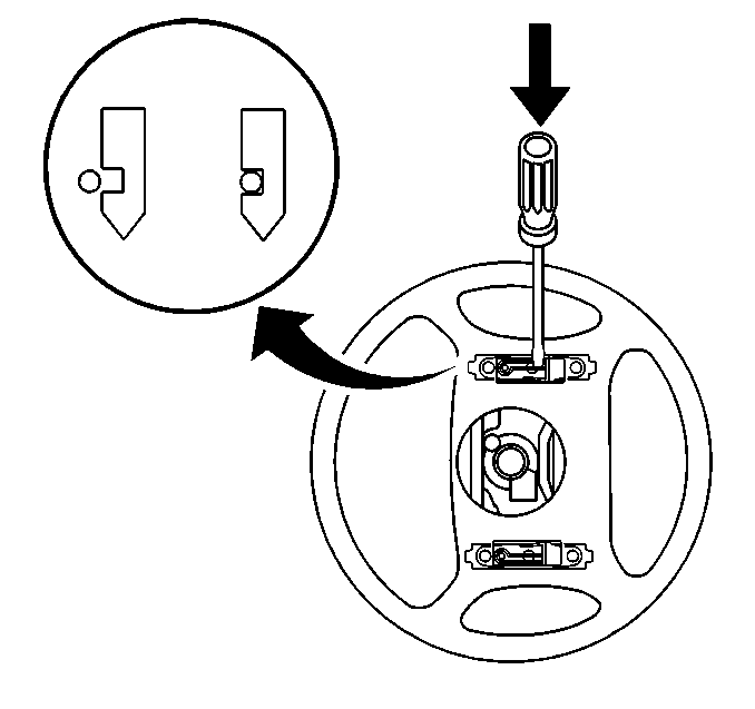
- Turn the steering wheel 90 degrees so that the side of the SIR module is at the 12 o’clock position in order to gain access to the holes behind the steering wheel.
- Insert a flat-bladed tool into the access hole and push the leaf spring in order to release the notched pin that retains the inflator module.
- Turn the steering wheel 180 degrees in order to gain access to the remaining access hole.
- Insert a screwdriver into the remaining hole and push the leaf spring in order to release the notched pin that retains the inflator module.
- Tilt the top of the inflator module rearward to gain access to the SIR wiring.
- Disconnect the SIR lead wire from the clip on the inflator module.
- Disconnect the SIR lead wire from the clip on the steering wheel.
- Disconnect the CPA retainer.
- Disconnect the electrical connector.
- Set the SIR module aside.
- Remove the horn plunger from the steering column by pressing inward to the stop and rotate the horn plunger 90 degrees.
- Remove the steering wheel retaining nut.
- Install the J 1859-A, Steering Wheel Puller, to the steering wheel.
- Remove the steering wheel using the J 1859-A.
- Remove the J 1859-A from the steering wheel.
- Remove the tilt lever.
- Remove the screws attaching the lower steering column cover to the steering column.
- Remove the lower steering column trim cover from the upper steering column trim cover.
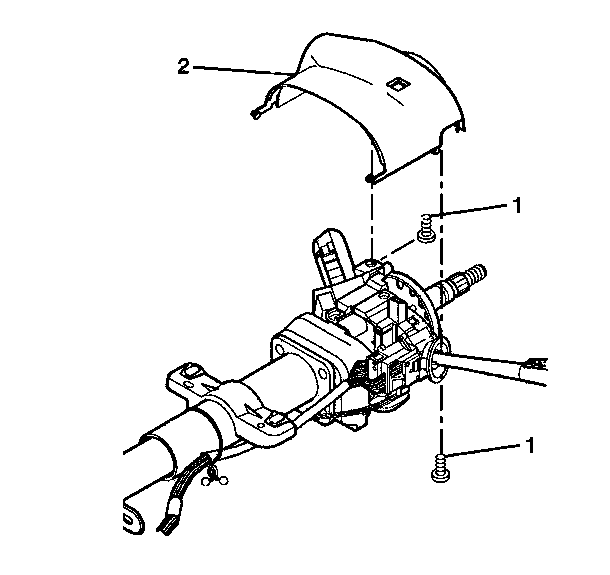
- Remove the upper steering column trim cover mounting screws (1).
- Lift the upper steering column trim cover to gain access to the lock cylinder access hole.
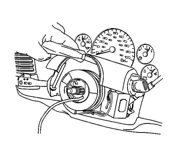
- Using a bent tip awl, insert the tip into the ignition lock cylinder access hole.
- Turn the ignition lock cylinder to the START position.
- Using the bent tip awl, push down on the ignition lock cylinder retaining pin.
- Release the ignition lock cylinder to the RUN position.
- Remove the ignition lock cylinder from the lock module by pulling the ignition lock cylinder away from the steering column.
- Remove the upper column cover.
- Inspect the part number (1) on the multifunction switch at the location shown in the illustration.
- Insert a small, pocket-sized, flat bladed screwdriver (2) into the small space between the hazard warning flasher switch housing (1) and the multifunction switch (3).
- Carefully tilt the screwdriver handle towards the instrument cluster. This will cause the blade of the screwdriver to pry open the space between the hazard warning flasher switch housing and the multifunction switch.
- While the space is pried open, pull the hazard warning flasher switch out of the multifunction switch. Discard the hazard warning flasher switch.
- Remove the rubber band and protective plastic wrapping from the new hazard warning flasher switch.
- Open the container of special grease included in the kit and apply it to the surfaces of the three triangle-shaped electrical contacts (1) on the side of the new hazard warning flasher switch. When properly applied, the surfaces of the three triangle-shaped electrical contacts must be completely covered and there should be no grease left in the container. DO NOT put any grease in the opening that contains the small metal return spring.
- Insert the hazard warning flasher switch into the opening of the multifunction switch and press down until it locks into place.
- Remove any excess grease that may appear around the base of the hazard warning flasher switch. Proceed to the next section "Reassemble Vehicle."
Important: Some of the illustrations included in this procedure show the steering column removed from the vehicle. Those illustrations are for reference purposes only. DO NOT remove the steering column from the vehicle to perform this repair procedure.
Caution: When you are carrying an undeployed inflator
module:
• Do not carry the inflator module by the wires or connector on the inflator
module. • Make sure the bag opening points away from you.
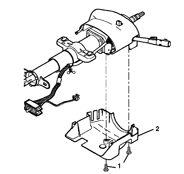
| 26.1. | Tilt the lower steering column trim cover down. |
| 26.2. | Slide the lower steering column trim cover backward in order to disengage the locking tabs. |
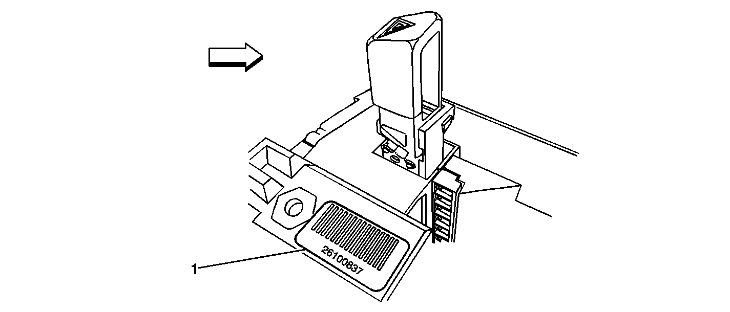
Important: The illustration above is for the purpose of identifying the barcode only. The actual location of the barcode on the switch may differ.
| • | If the part number is 26084051, 26084052, 26096834, 26096835, 26102157 or 26102158, no repair is required. Proceed to the section titled "Reassemble Vehicle." |
| • | If there is NO part number or barcode on the switch, no repair is required. Proceed to the section titled "Reassemble Vehicle." |
| • | If the part number or barcode on the switch is 26091775 or 26091776, proceed to the next step and replace the hazard warning flasher switch using part number 15177379. |
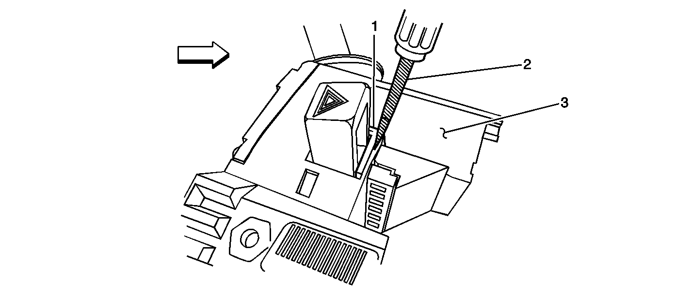
Important: Carefully review the above illustration to determine the exact location to insert the screwdriver in the next step.
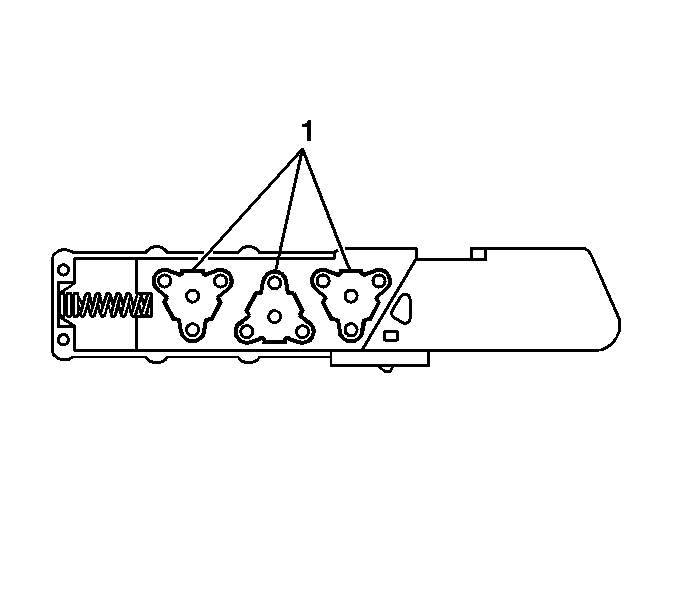
Notice: Do not touch the three triangle-shaped electrical contacts (1) on the side of the switch when removing the protective packaging, handling, or applying grease to the new hazard warning flasher switch in the next steps.
Important: The electrical contacts on the new hazard warning flasher switch require a special lubricant, which is included in the kit. Only apply this special lubricant as instructed in the next step. DO NOT use any other type of grease or lubricant.
Reassemble Vehicle
- Install the upper steering column cover.
- Insert the ignition lock cylinder through the upper shroud.
- Install the ignition lock cylinder to the lock module by doing the following:
- Install the upper steering column cover screws.
- Install the lower steering column trim cover to the upper steering column trim cover.
- Install the lower steering column cover screws.
- Install the tilt lever.
- Install the steering wheel to the steering shaft.
- Install the steering wheel retaining nut.
- Install the horn plunger to the steering column.
- Position the SIR module near the steering wheel.
- Connect the SIR electrical connector.
- Connect the CPA retainer to the SIR connector.
- Connect the SIR lead wire to the clip on the steering wheel.
- Connect the SIR lead wire to the clip on the inflator module.
- Press the inflator module into the steering wheel firmly enough that the module engages and latches the notched pins in the leaf springs.
- Rotate the steering wheel back into the straight position.
- Connect the I/P module yellow 2-way connector located under the I/P extension.
- Install the CPA to the I/P module yellow 2-way connector located under the I/P extension.
- Connect the steering wheel module yellow 2-way connector located at the base of the steering column.
- Install the CPA to the steering wheel module yellow 2-way connector located at the base of the steering column.
- Position the knee bolster trim panel to the I/P and install the attaching screws.
- Install the SIR fuse and install the fuse block cover.
- Be sure that the ignition is in the OFF position.
- Connect the negative battery.
| 3.1. | Align the positioning slot and locking tab slot on the lock module assembly to the positioning tab and locking tab on the ignition lock cylinder. |
| 3.2. | Push the ignition lock cylinder into the lock module assembly until the locking tab locks against the lock module. |
Tighten
Tighten the screws to 1.5 N·m (13 lb
in).
Important: The shift lever seal must be seated in the covers.
| 5.1. | Match the tab slots on the lower steering column trim cover with the locking tabs on the upper steering column trim cover. |
| 5.2. | Tilt the lower steering column trim cover up. |
| 5.3. | Slide the lower steering column trim cover forward until the locking tabs snap into the tab slots. |
Tighten
Tighten the screws to 3.5 N·m (31 lb
in).
Tighten
Tighten the steering wheel retaining nut to 41 N·m
(30 lb ft).
Important: Verify that the wiring is not exposed or trapped between the inflatable restraint steering wheel module and the steering wheel.
Tighten
Tighten the screws to 1.9 N·m(17 lb in).
Replacing the Multifunction Switch
This procedure describes how to replace ONLY the multifunction switch assembly. The new multifunction switch assembly will come complete with a new hazard warning flasher switch already installed.
DO NOT use this procedure if the results of the inspection procedure indicate that only the hazard warning flasher switch requires replacement.
Contained in this procedure are unique steps to address features or options such as cruise control, standard or tilt column, and a column-mounted automatic transmission lever.
Tools Required
J 1859-A Steering Wheel Puller
- Turn the ignition switch to the OFF position.
- Disconnect the negative battery.
- Remove the SIR fuse from the fuse block.
- Remove the screws attaching the driver's side knee bolster trim panel underneath the I/P and reposition the panel out of the way.
- Locate the driver's side yellow 2-way air bag electrical connector at the base of the steering column and remove the connector position assurance (CPA) from the connector.
- Disconnect the yellow 2-way electrical connector.
- If equipped, remove the tilt steering column lever.
- Turn the ignition switch to the RUN position to unlock the steering wheel.
- Turn the steering wheel 90 degrees so that the side of the SIR module is at the 12 o’clock position in order to gain access to the holes behind the steering wheel.
- Insert a flat-bladed tool into the access hole and push the leaf spring in order to release the notched pin that retains the inflator module.
- Turn the steering wheel 180 degrees in order to gain access to the remaining access hole.
- Insert a screwdriver into the remaining hole and push the leaf spring in order to release the notched pin that retains the inflator module.
- Tilt the top of the inflator module rearward to gain access to the SIR wiring.
- Disconnect the SIR lead wire from the clip on the inflator module.
- Disconnect the SIR lead wire from the clip on the steering wheel.
- Disconnect the CPA retainer.
- Disconnect the electrical connector.
- Set the SIR module aside.
- Remove the horn plunger from the steering column by pressing inward to the stop and rotate the horn plunger 90 degrees.
- Remove the steering wheel retaining nut.
- Install the J 1859-A, Steering Wheel Puller, to the steering wheel.
- Remove the steering wheel using the J 1859-A.
- Remove the J 1859-A from the steering wheel.
- Remove the tilt lever.
- Remove the screws attaching the lower steering column cover to the steering column.
- Remove the lower steering column trim cover from the upper steering column trim cover.
- Remove the upper steering column trim cover mounting screws (1).
- Lift the upper steering column trim cover to gain access to the lock cylinder access hole.
- Using a bent tip awl, insert the tip into the ignition lock cylinder access hole.
- Turn the ignition lock cylinder to the START position.
- Using the bent tip awl, push down on the ignition lock cylinder retaining pin.
- Release the ignition lock cylinder to the RUN position.
- Remove the ignition lock cylinder from the lock module by pulling the ignition lock cylinder away from the steering column.
- Remove the upper column cover.
- Disconnect the steering column electrical connectors.
- Disconnect the multifunction switch connectors from the steering column electrical connector.
- Remove the steering column wiring harness from the wiring harness strap.
- Remove the wire harness straps from the steering column wire harness.
- Remove the multifunction switch mounting screws.
- Remove the multifunction switch.
- Install the new multifunction switch as follows:
- Install the multifunction switch mounting screws.
- Connect the multifunction switch electrical connectors to the steering column electrical connector.
- Connect the steering column electrical connector to the I/P wire harness.
- Install the wire harness straps to the steering column wire harness.
- Install the steering column wire harness to the wiring harness strap.
- Install the upper steering column cover.
- Insert the ignition lock cylinder through the upper shroud.
- Install the ignition lock cylinder to the lock module by doing the following:
- Install the upper steering column cover screws.
- Install the lower steering column trim cover to the upper steering column trim cover.
- Install the lower steering column cover screws.
- Install the tilt lever.
- Install the steering wheel to the steering shaft.
- Install the steering wheel retaining nut.
- Install the horn plunger to the steering column.
- Position the SIR module near the steering wheel.
- Connect the SIR electrical connector.
- Connect the CPA retainer to the SIR connector.
- Connect the SIR lead wire to the clip on the steering wheel.
- Connect the SIR lead wire to the clip on the inflator module.
- Press the inflator module into the steering wheel firmly enough that the module engages and latches the notched pins in the leaf springs.
- Rotate the steering wheel back into the straight position.
- Connect the I/P module yellow 2-way connector located under the I/P extension.
- Install the CPA to the I/P module yellow 2-way connector located under the I/P extension.
- Connect the steering wheel module yellow 2-way connector located at the base of the steering column.
- Install the CPA to the steering wheel module yellow 2-way connector located at the base of the steering column.
- Position the knee bolster trim panel to the I/P and install the attaching screws.
- Install the SIR fuse and install the fuse block cover.
- Be sure that the ignition is in the OFF position.
- Connect the negative battery cable.
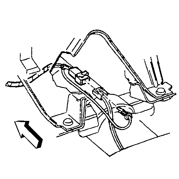
Important: Some of the illustrations included in this procedure show the steering column removed from the vehicle. Those illustrations are for reference purposes only. DO NOT remove the steering column from the vehicle to perform this repair procedure.

Caution: When you are carrying an undeployed inflator
module:
• Do not carry the inflator module by the wires or connector on the inflator
module. • Make sure the bag opening points away from you.

| 26.1. | Tilt the lower steering column trim cover down. |
| 26.2. | Slide the lower steering column trim cover backward in order to disengage the locking tabs. |


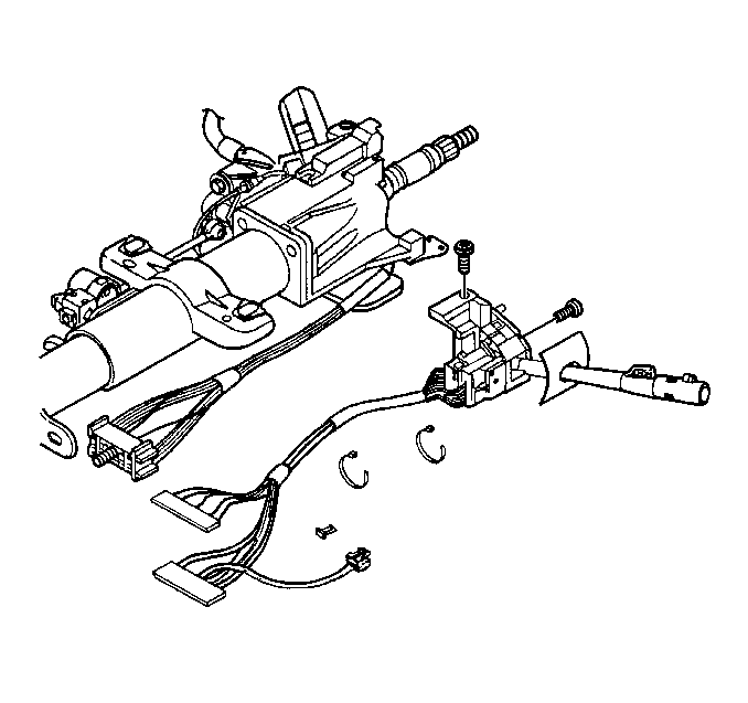
Important: The multifunction switch electrical contact must rest on the canceling cam assembly.
| 41.1. | Use a small blade screwdriver in order to compress the electrical contact. |
| 41.2. | Move the multifunction switch into position. |
Tighten
Tighten the multifunction switch mounting screws
to 6 N·m(53 lb in).
| 49.1. | Align the positioning slot and locking tab slot on the lock module assembly to the positioning tab and locking tab on the ignition lock cylinder. |
| 49.2. | Push the ignition lock cylinder into the lock module assembly until the locking tab locks against the lock module. |
Tighten
Tighten the screws to 1.5 N·m(13 lb in).
Important: The shift lever seal must be seated in the covers.
| 51.1. | Match the tab slots on the lower steering column trim cover with the locking tabs on the upper steering column trim cover. |
| 51.2. | Tilt the lower steering column trim cover up. |
| 51.3. | Slide the lower steering column trim cover forward until the locking tabs snap into the tab slots. |
Tighten
Tighten the screws to 3.5 N·m(31 lb in).
Tighten
Tighten the steering wheel retaining nut to 41 N·m(30
lb ft).
Important: Verify that the wiring in not exposed or trapped between the inflatable restraint steering wheel module and the steering wheel.
Tighten
Tighten the screws to 1.9 N·m (17 lb in).
Customer Reimbursement - For US
All customer requests for reimbursement for previous repairs for the recall condition will be handled by the Customer Assistance Center, not by dealers.
A General Motors Product Recall Customer Reimbursement Procedure Form is included with the customer letter.
Important: Refer to the GM Service Policies and Procedures Manual, section 6.1.12, for specific procedures regarding customer reimbursement and the form.
Customer Reimbursement - For Canada & Export
Customer requests for reimbursement of previously paid repairs to correct the condition addressed in this bulletin are to be submitted by April 30, 2006.
All reasonable customer paid receipts should be considered for reimbursement. The amount to be reimbursed will be limited to the amount the repair would have cost if completed by an authorized General Motors dealer.
When a customer requests reimbursement, they must provide the following:
| • | Proof of ownership at time of repair. |
| • | Original paid receipt confirming the amount of repair expense(s) that were not reimbursed, a description of the repair, and the person or entity performing the repair. |
Claims for customer reimbursement on previously paid repairs are to be submitted as required by WINS.
Important: Refer to the GM Service Policies and Procedures Manual, section 1.6.2, for specific procedures regarding customer reimbursement verification.
Courtesy Transportation
The General Motors Courtesy Transportation Program is intended to minimize customer inconvenience when a vehicle requires a repair that is covered by the New Vehicle Limited Warranty. The availability of courtesy transportation to customers whose vehicles are within the warranty coverage period and involved in a product recall is very important in maintaining customer satisfaction. Dealers are to ensure that these customers understand that shuttle service or some other form of courtesy transportation is available and will be provided at no charge. Dealers should refer to the General Motors Service Policies and Procedures Manual for courtesy transportation guidelines.
Claim Information
Submit a Product Recall Claim with the information indicated below:
Repair Performed | Part Count | Part No. | Parts Allow | CC-FC | Labor Op | Labor Hours | Net Item |
|---|---|---|---|---|---|---|---|
Inspect Only - No Further Action Required | 0 | N/A | N/A | MA-96 | V1341 | 0.4 | N/A |
Inspect & Replace Hazard Warning Switch | 1 | -- | * | MA-96 | V1342 | 0.4 | N/A |
Inspect & Replace Multifunction Switch | 1 | -- | * | MA-96 | V1343 | 0.5 | N/A |
Courtesy Transportation (for vehicles covered under the New Vehicle Limited Warranty) | N/A | N/A | N/A | MA-96 | ** | N/A | *** |
Customer Reimbursement (Canadian & Export Dealers/US CAC) | N/A | N/A | N/A | MA-96 | V1344 | 0.2 | **** |
* The "Parts Allowance" should be the sum total of the current GMSPO Dealer net price plus applicable Mark-Up or Landed Cost Mark-Up (for Export) for the hazard warning switch or the multifunction switch needed to complete the repair. ** Courtesy transportation using normal labor operations for courtesy transportation as indicated in the GM Service Policies and Procedures Manual. *** The amount identified in the "Net Item" column should represent the actual dollar amount for courtesy transportation for vehicles still covered under the New Vehicle Limited Warranty. **** The amount identified in the "Net Item" column should represent the dollar amount reimbursed to the customer. | |||||||
Refer to the General Motors WINS Claims Processing Manual for details on Product Recall Claim Submission.
Customer Notification -- For US and Canada
General Motors will notify customers of this recall on their vehicle (see copy of customer letter included with this bulletin).
Customer Notification -- For Export
Letters will be sent to known owners of record located within areas covered by the US National Traffic and Motor Vehicle Safety Act. For owners outside these areas, dealers should notify customers using the attached sample letter.
Dealer Recall Responsibility -- For US and Export (US States, Territories, and Possessions)
The US National Traffic and Motor Vehicle Safety Act provides that each vehicle which is subject to a recall of this type must be adequately repaired within a reasonable time after the customer has tendered it for repair. A failure to repair within sixty days after tender of a vehicle is prima facie evidence of failure to repair within a reasonable time. If the condition is not adequately repaired within a reasonable time, the customer may be entitled to an identical or reasonably equivalent vehicle at no charge or to a refund of the purchase price less a reasonable allowance for depreciation. To avoid having to provide these burdensome remedies, every effort must be made to promptly schedule an appointment with each customer and to repair their vehicle as soon as possible. In the recall notification letters, customers are told how to contact the US National Highway Traffic Safety Administration if the recall is not completed within a reasonable time.
Dealer Recall Responsibility -- All
All unsold new vehicles in dealers' possession and subject to this recall MUST be held and inspected/repaired per the service procedure of this recall bulletin BEFORE customers take possession of these vehicles.
Dealers are to service all vehicles subject to this recall at no charge to customers, regardless of mileage, age of vehicle, or ownership, from this time forward.
Customers who have recently purchased vehicles sold from your vehicle inventory, and for which there is no customer information indicated on the dealer listing, are to be contacted by the dealer. Arrangements are to be made to make the required correction according to the instructions contained in this bulletin. A copy of the customer letter is provided in this bulletin for your use in contacting customers. Recall follow-up cards should not be used for this purpose, since the customer may not as yet have received the notification letter.
In summary, whenever a vehicle subject to this recall enters your vehicle inventory, or is in your dealership for service in the future, please take the steps necessary to be sure the recall correction has been made before selling or releasing the vehicle.
GENERAL MOTORS PRODUCT RECALL CUSTOMER REIMBURSEMENT PROCEDURE
If you have paid to have this recall condition corrected prior to receiving this notification, you may be eligible to receive reimbursement.
Requests for reimbursement may include parts, labor, fees and taxes. Reimbursement may be limited to the amount the repair would have cost if completed by an authorized General Motors dealer.
Your claim will be acted upon within 60 days of receipt.
If your claim is:
| • | Approved, you will receive a check from General Motors. |
| • | Denied, you will receive a letter from General Motors with the reason(s) for the denial, or |
| • | Incomplete, you will receive a letter from General Motors identifying the documentation that is needed to complete the claim and offered the opportunity to resubmit the claim when the missing documentation is available. |
Please follow the instructions on the Claim Form provided on the reverse side to file a claim for reimbursement. If you have questions about this reimbursement procedure, please call the toll-free telephone number provided at the bottom of the form. If you need assistance with any other concern, please contact the appropriate Customer Assistance Center at the number listed below. The Customer Assistance Center hours of operation are from 8:00 AM - 11:00 PM eastern standard time Monday through Friday
Division | Number | Text Telephones (TTY) |
|---|---|---|
Chevrolet | 1-800-630-2438 | 1-800-833-2622 |
GMC | 1-866-996-9463 | 1-800-462-8583 |
GENERAL MOTORS PRODUCT PROGRAM CUSTOMER REIMBURSEMENT CLAIM FORM
THIS SECTION TO BE COMPLETED BY CLAIMANT | |||||||||||||
|---|---|---|---|---|---|---|---|---|---|---|---|---|---|
Date Claim Submitted:
Vehicle Identification Number (VIN):
Mileage at Time of Repair:
Date of Repair:
Claimant Name (please print):
Street Address or PO Box Number:
City, State, ZIP Code:
Daytime Telephone Number (include Area Code):
Evening Telephone Number (include Area Code):
Amount of Reimbursement Requested: $
THE FOLLOWING DOCUMENTATION MUST ACCOMPANY THIS CLAIM FORM Original or clear copy of all receipts, invoices and/or repair orders that show:
My signature to this document attests that all attached documents are genuine and I request reimbursement for the expense I incurred for the repair covered by this special policy. Claimant's Signature:
| |||||||||||||
Please mail this claim form and the required documents to:
General Motors Corporation
P.O. Box 33170
Detroit, MI 48232-5170
All recall reimbursement questions should be directed to the following number: 1-800-204-0261.
April 2005Dear General Motors Customer:
This notice is sent to you in accordance with the requirements of the National Traffic and Motor Vehicle Safety Act.
Reason For This Recall
General Motors has decided that a defect, which relates to motor vehicle safety, exists in certain 2001-2002 Chevrolet Astro and GMC Safari vehicles. On some of these vehicles, the stop lamps and rear hazard lamps may become inoperative. The usage factors that increase the possibility of this condition occurring include frequency and length of brake applications, frequency of trailer towing with brake applications, and exposure to high ambient temperatures. The center high mounted stop lamp and turn signal lamp functionality are not affected. The loss of stop lamps and/or rear hazard lamps could fail to warn a following driver that the vehicle is braking and/or is stopped and could lead to a vehicle accident.
What Will Be Done
Your GM dealer will inspect and replace the hazard warning flasher switch, if necessary. In a small number of vehicles, the multifunction switch will require replacement. This service will be performed for you at no charge .
How Long Will The Repair Take?
This inspection and service correction will take approximately 25-30 minutes. However, due to service scheduling requirements, your dealer may need your vehicle for a longer period of time.
Contacting Your Dealer
To limit any possible inconvenience, we recommend that you contact your dealer as soon as possible to schedule an appointment for this repair. By scheduling an appointment, your dealer can ensure that the necessary parts will be available on your scheduled appointment date. Should your dealer be unable to schedule a service date within a reasonable time, you should contact the appropriate Customer Assistance Center at the listed number below. The Customer Assistance Center’s hours of operation are from 8:00 AM to 11:00 PM, EST, Monday through Friday.
Division | Number | Text Telephones (TTY) |
|---|---|---|
Chevrolet | 1-800-630-2438 | 1-800-833-2622 |
GMC | 1-866-996-9463 | 1-800-462-8583 |
Puerto Rico - English | 1-800-496-9992 |
|
Puerto Rico - Español | 1-800-496-9993 |
|
Virgin Islands | 1-800-496-9994 |
|
Guam | 1-671-648-8650 |
|
If, after contacting the appropriate customer assistance center, you are still not satisfied that we have done our best to remedy this condition without charge and within a reasonable time, you may wish to write the Administrator, National Highway Traffic Safety Administration, 400 Seventh Street SW, Washington, DC 20590 or call 1-888-327-4236.
Customer Reply Form
The enclosed customer reply form identifies your vehicle. Presentation of this form to your dealer will assist in making the necessary correction in the shortest possible time. If you no longer own this vehicle, please let us know by completing the form and mailing it back to us.
Customer Reimbursement
The enclosed form explains what reimbursement is available and how to request reimbursement if you have paid for repairs for the recall condition.
Courtesy Transportation
If your vehicle is within the New Vehicle Limited Warranty your dealer may provide you with shuttle service or some other form of courtesy transportation while your vehicle is at the dealership for this repair. Please refer to your Owner’s Manual and your dealer for details on Courtesy Transportation.
Owner Center Online
This free online service offers vehicle and ownership related information and tools tailored to your specific vehicle. To get the most personalized information for your vehicle, visit www.mygmlink.com , and enter your vehicle's 17-character vehicle identification number (VIN) shown on the enclosed customer reply form.
Federal regulation requires that any vehicle lessor receiving this recall notice must forward a copy of this notice to the lessee within ten days.
We are sorry to cause you this inconvenience; however, we have taken this action in the interest of your safety and continued satisfaction with our products.
General Motors Corporation
Enclosure
05013
