LOW ALTERNATOR OUTPUT (MAYBE MISSING RESISTOR WIRE)

VEHICLES AFFECTED: 1987 P2 AND P3 W/L25 (VIN CODE T) AND LL4 (VIN CODE J) ENG
Some of the above subject vehicles may experience low alternator output when the engine speed is below 1500 RPM. This condition may be due to a lack of a 10 ohm resistance (22 gage) excitation wire which supplies current between the ignition switch and the bulkhead connector.
Effective with vehicles manufactured after April 1, 1987 (S/N H3503820-GMC and S/N H3320340-Chevy) all above subject vehicles were produced with a revised chassis electrical harness which incorporated this alternator resistance excitation wire
To inspect for this condition, a brown with a white stripe wire should run from the ignition switch connector to the bulkhead connector. If this wire is not found, an excitation wire should be installed. Also, any vehicle which is reported to have poor alternator performance (especially if operated at lower engine RPM's) should be inspected for this condition prior to alternator or battery replacement.
To install the excitation circuit, the following service procedure should be followed:
1. Disconnect the battery ground cable.
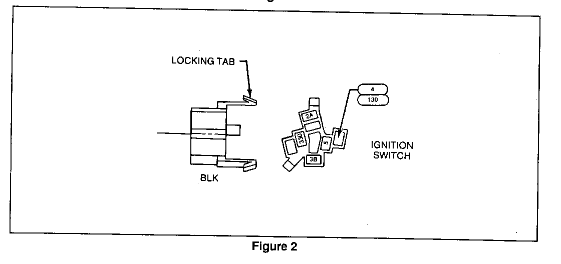
2. Disconnect the black ignition switch connector from the ignition cylinder switch by pushing down on the locking tabs and pulling.
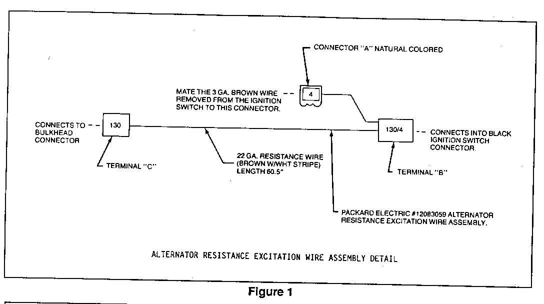
3. Remove the existing 3 gage brown wire from the black ignition switch connector and plug it into the 1-way natural colored connector "A" on the service assembly P/N 12083059. Listen for a "click" sound, then gently tug to verify the connection is seated. Needle nose pliers may be required to insert the terminal (Figures 1 and 2).
4. Plug in the number 130 double terminated wire (terminal "B") into the ignition switch connector where the 3 gage brown wire was removed in Step 3. Reconnect the ignition switch connector to the back of the ignition cylinder switch (Figure 2).
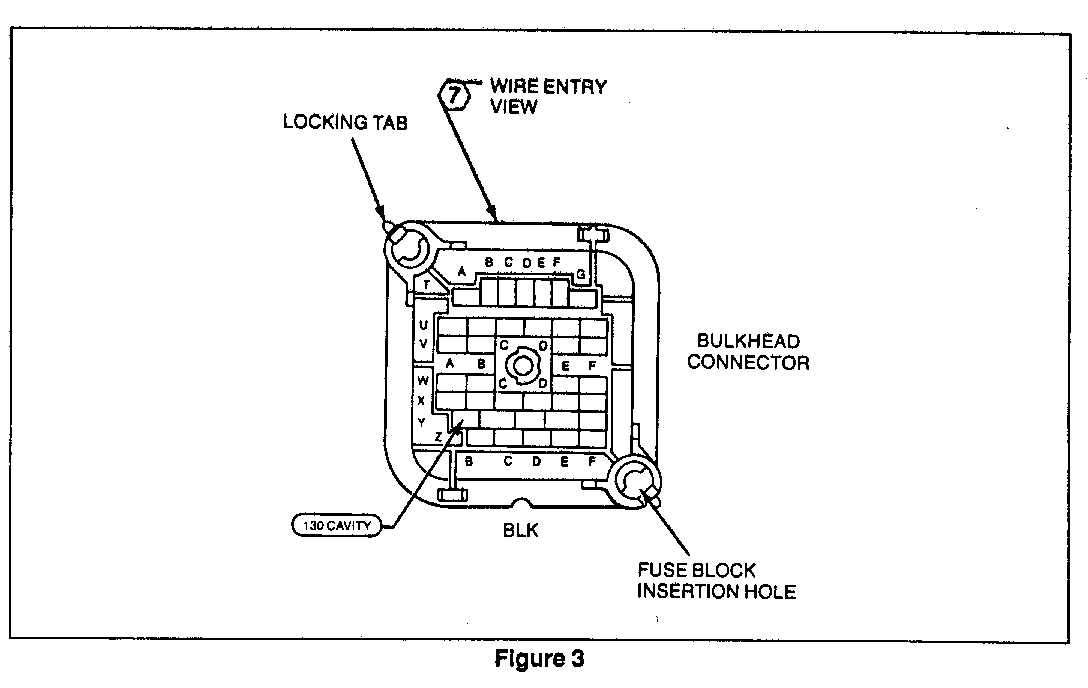
5. Remove the fuse block from the bulkhead connector by releasing the corner locking tabs and pulling. A screwdriver may be required to release the corner locking tabs.
6. Plug terminal "C" into the number 130 cavity where row "Y" intersects column "B" in the bulkhead connector (Figure 3). Listen for a "click" sound, then gently tug to verify the connection is seated. Needle nose pliers may be required to insert the terminal (Figure 3).
7. Reconnect the fuse block into the locking tabs and insertion holes in the bulkhead connector.
8. DO NOT shorten or cut the excess wire due to its resistance value. Loop the wire and secure it to the main harness with electrical tape (Figure 1).
9. Reconnect the battery ground cable.
PARTS INFORMATION:
PART NUMBER DESCRIPTION QUANTITY ----------- ----------- -------- 12083059 Alternator Resistance Excitation 1 Wire Assembly


General Motors bulletins are intended for use by professional technicians, not a "do-it-yourselfer". They are written to inform those technicians of conditions that may occur on some vehicles, or to provide information that could assist in the proper service of a vehicle. Properly trained technicians have the equipment, tools, safety instructions and know-how to do a job properly and safely. If a condition is described, do not assume that the bulletin applies to your vehicle, or that your vehicle will have that condition. See a General Motors dealer servicing your brand of General Motors vehicle for information on whether your vehicle may benefit from the information.
