DUTCH DOOR WATER ENTRY (SERVICE PROCEDURES)

SUBJECT: DUTCH DOOR WATER ENTRY (SERVICE PROCEDURES)
VEHICLES AFFECTED: 1992-93 "M/L" VANS WITH RPO E54
Owners of some 1992-93 M/L Vans equipped with Dutch Doors may comment on water entry into the rear door area. There are four different water leaks, possible on the new Dutch Door System:
1. Liftgate hinge/glass leaks
2. Compression leaks
3. Carrier leaks
4. Marriage leaks
Important: Verify that all the body seams on the perimeter of the liftgate frame opening and the vehicle body are properly sealed, especially by the liftgate strut area. If areas need additional sealing, apply a clear silicone (P/N 10950893 or equivalent) to the exposed areas.
SERVICE PROCEDURE:
Liftgate Hinge/Glass Leaks
Water enters into the rear of the vehicle through the liftgate hinge area or around the liftgate glass seal.
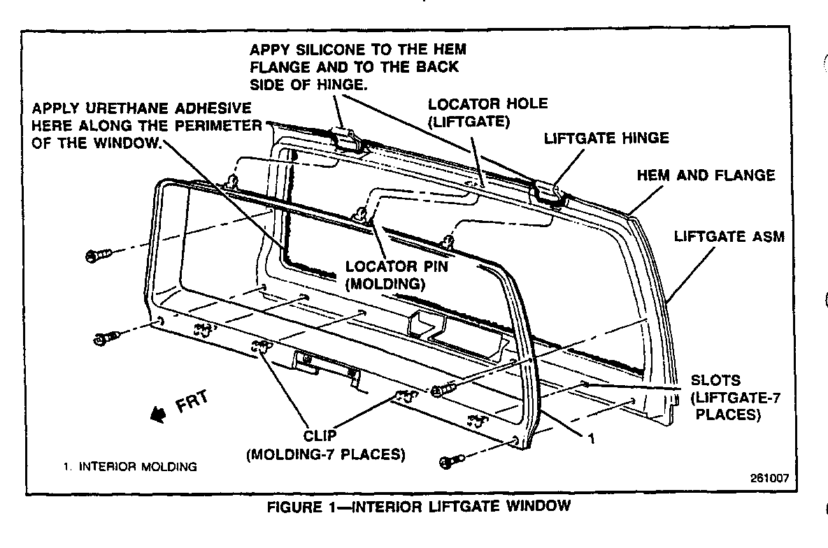
1. To repair this condition it will be necessary to apply a clear flexible silicone (P/N 10950893 or equivalent) to the surrounding hinge area and to the upper liftgate hem-flange (Figure 1) and/or black urethane adhesive (P/N 12345632 or equivalent) along the perimeter of the interior of the rear liftgate window (It will be necessary to remove the liftgate interior moulding - Figure 1).
Important: Before closing the liftgate or water testing the vehicle, allow the sealant(s) to properly cure per the manufacturer's recommendations.
Compression Leaks
Water enters the vehicle on the left or right side of the liftgate or at the top of the liftgate at roof level.
1. Remove the rear air conditioning duct if equipped.
2. Remove the interior roof moulding.
3. Remove the screws from the quarter panel side mouldings in order to gain access to the weatherstrip flange.
4. Remove the lower carpet sill plate.
5. Remove the weatherstrip from the flange.
6. Bend the flange approximately 3 mm (1/8 inch) (in a uniform manner) rearward (towards you) approximately 7.6-10.0 cm (3-4 inches) to the left and to the right of leak area.
Important: Use caution when bending the flange or you may distort the metal and direct the leak to some other entry point. Use sheet metal bending pliers or equivalent to bend the flange.
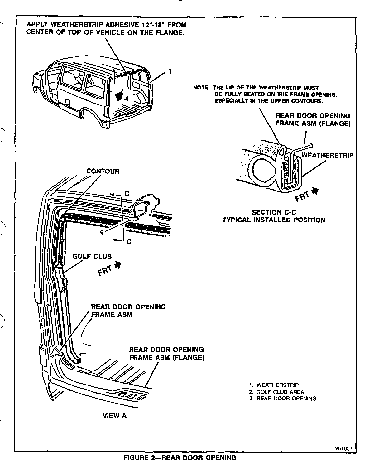
7. Apply weatherstrip adhesive (P/N 12345632 or equivalent) to the flange area, 30-46 cm (12-18 inches) from the centreline of the top of the vehicle (Figure 2) and install the weatherstrip.
Apply weatherstrip adhesive to the contours of the flange and verify that the weatherstrip is fully seated in the contour (Figure 2).
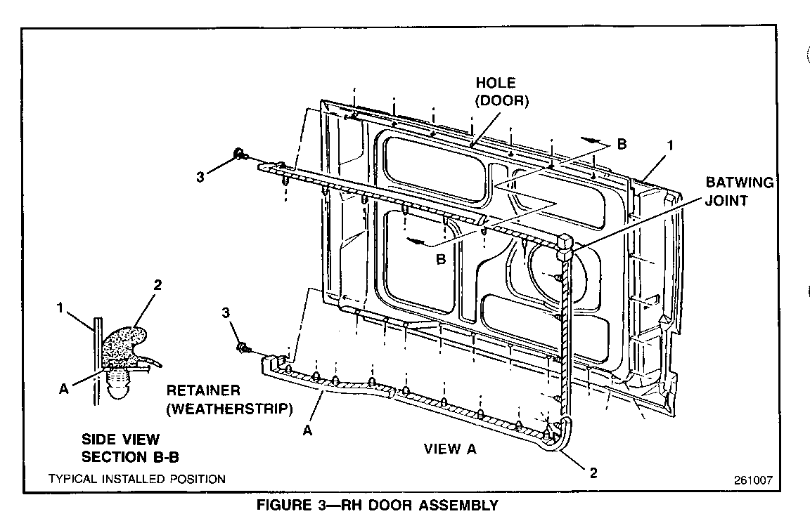
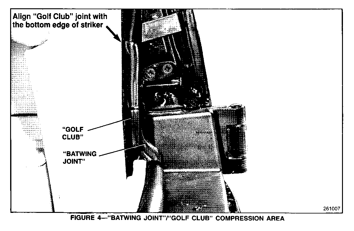
8. Verify that the weatherstrip "Golf Club" and "Batwing Joint" are positioned correctly by closing one lower door and checking for a good compression fit (no gaps), repeat for other side (see Figures 2, 3 and 4).
9. Install the lower carpet sill plate.
10. Install the rear quarter panel screws.
11. Install the interior roof moulding.
12. Install the rear air conditioning duct if equipped.
Carrier Leaks
Water enters the vehicle at the floor area either on the carpet or under the carpet. This can be seen by removing the rear sill plate which holds the carpet down. The leak will usually enter through the centre of the weatherstrip.
1. Remove the rear air conditioning duct if equipped.
2. Remove the interior roof moulding.
3. Remove the screws from the quarter panel side mouldings to gain access to the weatherstrip flange.
4. Remove the lower carpet sill plate.
5. Apply weatherstrip adhesive (P/N 12345632 or equivalent) to the flange area, 30-46 cm (12-18 inches) from the centreline of the vehicle and install the weatherstrip.
Apply weatherstrip adhesive to the contours of the flange and verify that the weatherstrip is fully seated in the contour (Figure 2).
Important: Make sure the lip of the weatherstrip is fully seated on the frame opening, especially in the upper contours.
6. Close the rear doors and align the weatherstrip to insure proper mating (Batwing Joint and at the Golf Club Areas, Figures 2, 3 and 4).
7. Install the lower carpet sill plate.
8. Install the rear quarter panel screws.
9. Install the interior roof moulding.
10. Install the rear air conditioning duct if equipped.
11. Use a mild detergent (i.e. Dishwasher soap or equivalent) to soap the rear weatherstrips at the "Batwing Joint" and "Golf Club" area. This will allow the new weatherstrip to slide into position until the final shape has set.
Marriage Leaks
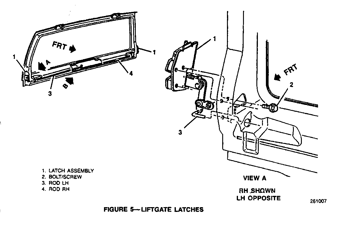
Water enters the doors at the top of the rear doors and runs down the rear door trim panels. This may be caused by a poor relationship at the "Batwing Joint" and the "Golf Club" area (Figures 2, 3, 4 and 5).
1. Verify that the liftgate is flush with the body of the vehicle.
2. Remove the liftgate interior handle and trim panel.
3. Adjust the liftgate outer latch assemblies: Loosen the 3 screws (3 per side) and close the door tight. Retighten the screws, this will insure proper adjustment (the liftgate latches are self adjusting).
4. Close the rear doors and align the weatherstrip to the liftgate to insure proper mating (Batwing Joint and at the Golf Club area, Figures 2, 3 an 4). Alignment can be accomplished by fitting the weatherstrip on the flange while closing one lower door. The "Batwing" should overlap the "golf club" approximately 38 mm (1.5 inches) from the lower leg of the "golf club".
5. Verify that the rear door weatherstrip at the "Batwing Joint" is not being trapped under the rear door hinge covers that lay on top of the door surfaces. If this occurs, remove the three screws that hold the cover in place and reposition the hinge covers so that trapping does not occur. There is a notch cut out of the hinge cover moulding so that the "Batwing Joint" on the rear doors does not become trapped.
6. Install the liftgate interior handle and trim panel.
PARTS INFORMATION:
Part Number Description ----------- ----------- 10950893 Clear Silicone
12345632 Black Urethane Adhesive
WARRANTY INFORMATION:
Operation Description Labour Time --------------------- ----------- Liftgate Hinge/Glass Leaks 0.4 Compression Leaks 0.6** Carrier Leaks 0.6** Marriage Leaks 0.3 Prep And Water Test 0.2*
*The Prep and Water test Labour Operation can only be used one time when performing this bulletin.
**When Compression Leaks is used in conjunction with Carrier Leaks, reduce total time by 0.3 hr.
Note: Labour operation is coded to base vehicle coverage in the warranty system.
General Motors bulletins are intended for use by professional technicians, not a "do-it-yourselfer". They are written to inform those technicians of conditions that may occur on some vehicles, or to provide information that could assist in the proper service of a vehicle. Properly trained technicians have the equipment, tools, safety instructions and know-how to do a job properly and safely. If a condition is described, do not assume that the bulletin applies to your vehicle, or that your vehicle will have that condition. See a General Motors dealer servicing your brand of General Motors vehicle for information on whether your vehicle may benefit from the information.
