DRIVELINE NOISE-RESEMBLES 'BAD AXLE BEARING'

SUBJECT: DRIVELINE NOISE WHICH RESEMBLES "BAD AXLE BEARINGS" (INSTALL NEW TRANSFER CASE CHAIN)
VEHICLES AFFECTED: 1990-93 L-VANS W/ALL WHEEL DRIVE
CONDITION:
--------- Some owners of 1990-93 L-vans (AWD) may comment about a drive line noise/rumble under light or moderate loads while driving. This condition resembles abnormal axle bearing noise when driving under light or moderate loads, and usually occurs on acceleration from 47 to 54 mph. The noise/rumble that this bulletin addresses will go away by letting up on the accelerator pedal.
CAUSE:
----- The Borg Warner 4472 Transfer Case is designed with a "random variable pitch" chain, which causes a high frequency tonal sound/noise called "rumble".
CORRECTION:
---------- A new transfer case chain (P/N 15963558) is available which incorporates straight pitch links instead of variable pitch links. The straight pitch chain will reduce the tonal noise called rumble. Vehicles built after the following VIN breakpoints have the new style chain in the transfer case installed in production:
Make VIN
GMC PB521795 Chevrolet PB152925
SERVICE PROCEDURES
Important: Ensure front and rear propeller shafts are marked relative to other drive shaft components before disassembly. These components are match balanced and MUST be reassembled in the same relationship to each other to maintain proper balance. Refer to Section 4A of the appropriate M/L Service Manual for further information.
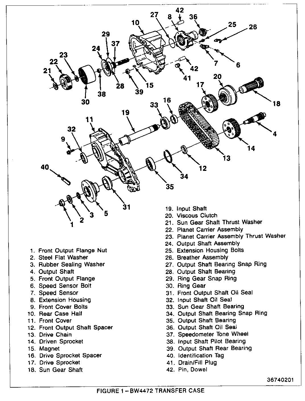
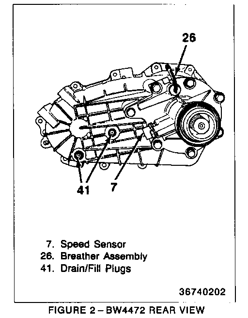
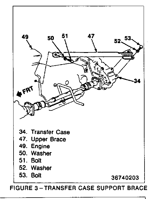
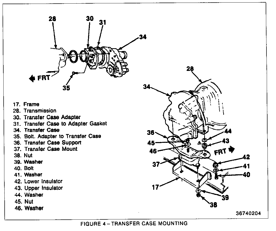
REMOVE OR DISCONNECT FROM VEHICLE (Figure 1, 2,3, and 4)
1. Disconnect the negative battery cable from the battery. Refer to Section OB of the M/L Service Manual.
2. Raise the vehicle and support with safety stands. Refer to Section OA of the appropriate M/L Service Manual.
3. Place a drain pan under the transfer case drain plug and remove the drain plug (41).
o allow oil to drain completely before re-installing the drain plug.
o tighten the oil drain plug (41) to 9 N.m (80 lbs. in.).
4. Remove the front and rear propeller shafts. Refer to Section 4A of the appropriate M/L Service Manual.
5. Disconnect breather vent tube (26) from the top of the transfer case.
6. Disconnect the electrical plug from the Speed Sensor (7)
o connection at the transfer case.
o support transfer case with a jack.
7. Disconnect the transfer case support brace (47) by removing the bolts and washers (52 and 53) at the transfer case only.
8. Disconnect and remove the mounting nuts and washers (38 and 39) from the support bracket (17).
9. Disconnect and remove the adapter to transfer case bolts (35) from the rear of the transfer case adapter.
10. Remove the transfer case to adapter gasket (31) between the adapter (30) and transfer case (34).
DISASSEMBLY OF THE TRANSFER CASE
Clean the transfer case using solvent and a stiff brush.
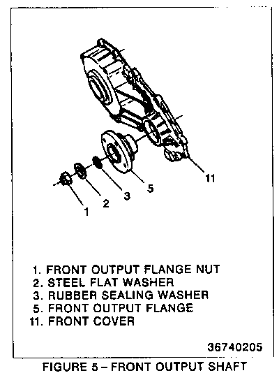
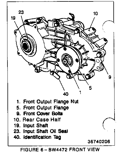
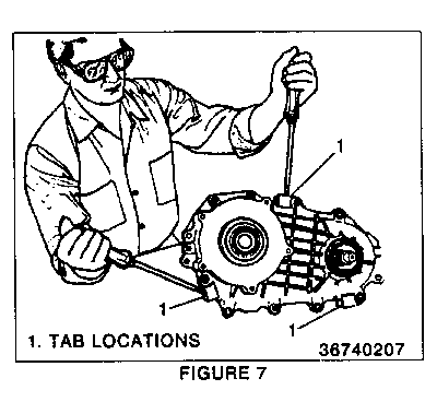
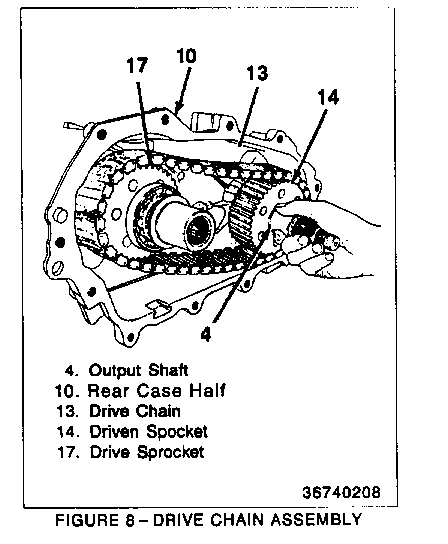
REMOVE OR DISCONNECT (Figure 1, 5, 6,7, and 8)
1. Remove the front output flange nut (1), steel flat washer (2) and rubber sealing washer (3) from the front output shaft (4).
2. Remove the front output flange (5) from the front output shaft (4)
3. Remove the front cover bolts (9) from the rear case half (10).
o The identification tag (40) is an aluminum tag attached under one of the self-tapping case bolts. Every attempt should be made to keep the identification tag with the unit.
4. Remove the case half dowel pins (42), quantity of 2, by using a mallet and punch.
5. Remove the front cover (11) by prying on the tabs (1) provided on the case halves.
6. Remove the drive chain (13) from the output shaft (4), driven sprocket (14) and the drive sprocket (17).
7. Remove gasket material thoroughly from the both halves of the transfer case.
CLEANING AND INSPECTION
Clean
Make sure the internal gears, sprockets and shafts are clean and free of foreign material.
Inspect
1. Inspect for excessive wear or damage, spalling, cracks, or corrosion on internal parts of the transfer case.
2. Inspect case half for damaged or warped mating surfaces, cracks, porosity, or damaged thread holes.
ASSEMBLY OF THE TRANSFER CASE (Figure 5, 6, and 8)
During assembly of the transfer case, lube all necessary parts with Dextron II E Automatic Transmission Fluid or (GM P/N 9985286).
1. Install the new style drive chain (P/N 15963558) (13) onto the driven sprocket (14) and over the drive sprocket (17).
2. Apply a 1/8-inch bead of Sealer * (GM P/N 12345997 black sealer) or equivalent to the rear case half (10) front cover sealing surface.
Important: DO NOT USE RTV SEALER (GM P/N 1052366) THAT IS CALLED OUT IN THE M/L SERVICE MANUAL OR UNIT REPAIR MANUAL.
3. Install the front cover (11) and bolts (9) to the rear case half (10).
o Tighten front cover bolts (9) to 42 N.m (30 lbs. ft.).
5. Install the front output flange (5) to the front output shaft (4).
6. Install the rubber sealing washer (3), steel flat washer (2), and front output flange nut (1).
o Tighten output flange nut (1) to 108 N.m. (80 lbs. ft.).
INSTALL OR CONNECT TRANSFER CASE TO VEHICLE (Figure 1, 2,3, and 4)
1. Make sure all gasket surfaces are clean and free of grease and oil
2. Install a new transfer case to adapter gasket (31) (P/N 15642511), if needed. Use gasket sealer to hold gasket in place.
3. Support transfer case with a jack.
4. Install the transfer case to transfer case adapter behind the transmission.
5. Install bolts (35) through the transfer case adapter (30) to the transfer case.
o Tighten bolts (35) to 52 N.m (38 lbs. ft.).
6. Remove jack from transfer case.
7. Install washers and nuts (38 and 39) to transfer case mount (37) bolts to support brace (17).
o Tighten nuts (39) to 35 N.m (26 lbs. ft.).
8. Connect support brace (47), washers (52 and 53)
o Tighten bolts (53) to 128 N.m (94 lbs. ft.).
9. Connect electrical connections.
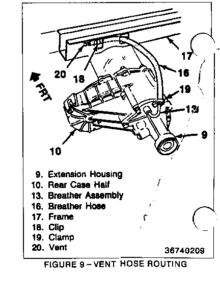
10. Connect breather hose (16) to vent tube (13).
o The breather hose must be free of kinks and routed correctly as shown in Figure 9.
11. Install front and rear propeller shafts. Refer to Section 4A.
12. Remove filler plug (41) from transfer case.
13. Fill transfer case with Dextron II E automatic transmission fluid (GM P/N 12345881) until oil level is at the bottom of filler plug hole (1.5 qts., 1.4 liter).
14. Install fill plug (41).
o Tighten fill plug (41) to 9 N.m (80 lbs. in.).
15. Lower the vehicle.
16. Connect the negative battery cable to the battery. Refer to Section OB.
SERVICE PARTS INFORMATION
Part Number Description Qty ----------- ----------- --- 12345997 Sealer 1 15963558 Chain, Transfer Case 1 15642511 Gasket, Transfer Adapter 1
WARRANTY INFORMATION
For vehicles repaired under warranty, use:
Labor Op Labor Time -------- ---------- K4400 See applicable Labor Time Guide
General Motors bulletins are intended for use by professional technicians, not a "do-it-yourselfer". They are written to inform those technicians of conditions that may occur on some vehicles, or to provide information that could assist in the proper service of a vehicle. Properly trained technicians have the equipment, tools, safety instructions and know-how to do a job properly and safely. If a condition is described, do not assume that the bulletin applies to your vehicle, or that your vehicle will have that condition. See a General Motors dealer servicing your brand of General Motors vehicle for information on whether your vehicle may benefit from the information.
