Removal Procedure
- Remove two-thirds of the brake fluid from the master cylinder.
- Raise the vehicle. Refer to Lifting and Jacking the Vehicle in General Information.
- Remove the tire and wheel assembly. Refer to Wheel Removal in Tires and Wheels.
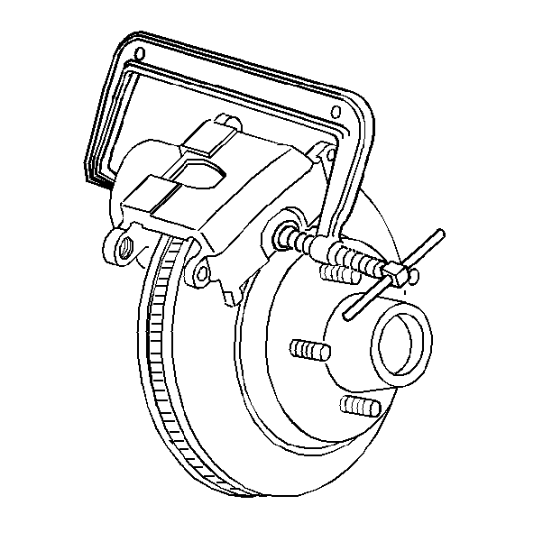
- Position a C-clamp around the outer pad and the caliper. Tighten the clamp until the piston bottoms in its bore.
- Remove the C-clamp.
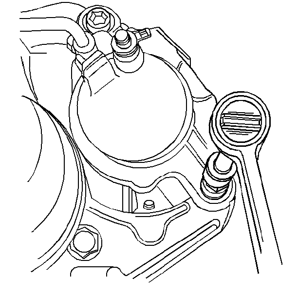
- Remove the brake hose from the caliper.
- Remove the mounting bolts.
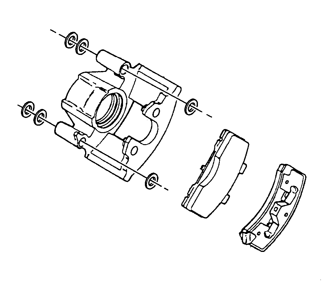
- Remove the brake pads. Refer to Brake Pads Replacement .
- Remove the caliper assembly.
- Remove the bushings.
- Remove the sleeves (RWD only).
- Replace any corroded bolts or sleeves. Do not attempt to polish away any corrosion.
Installation Procedure
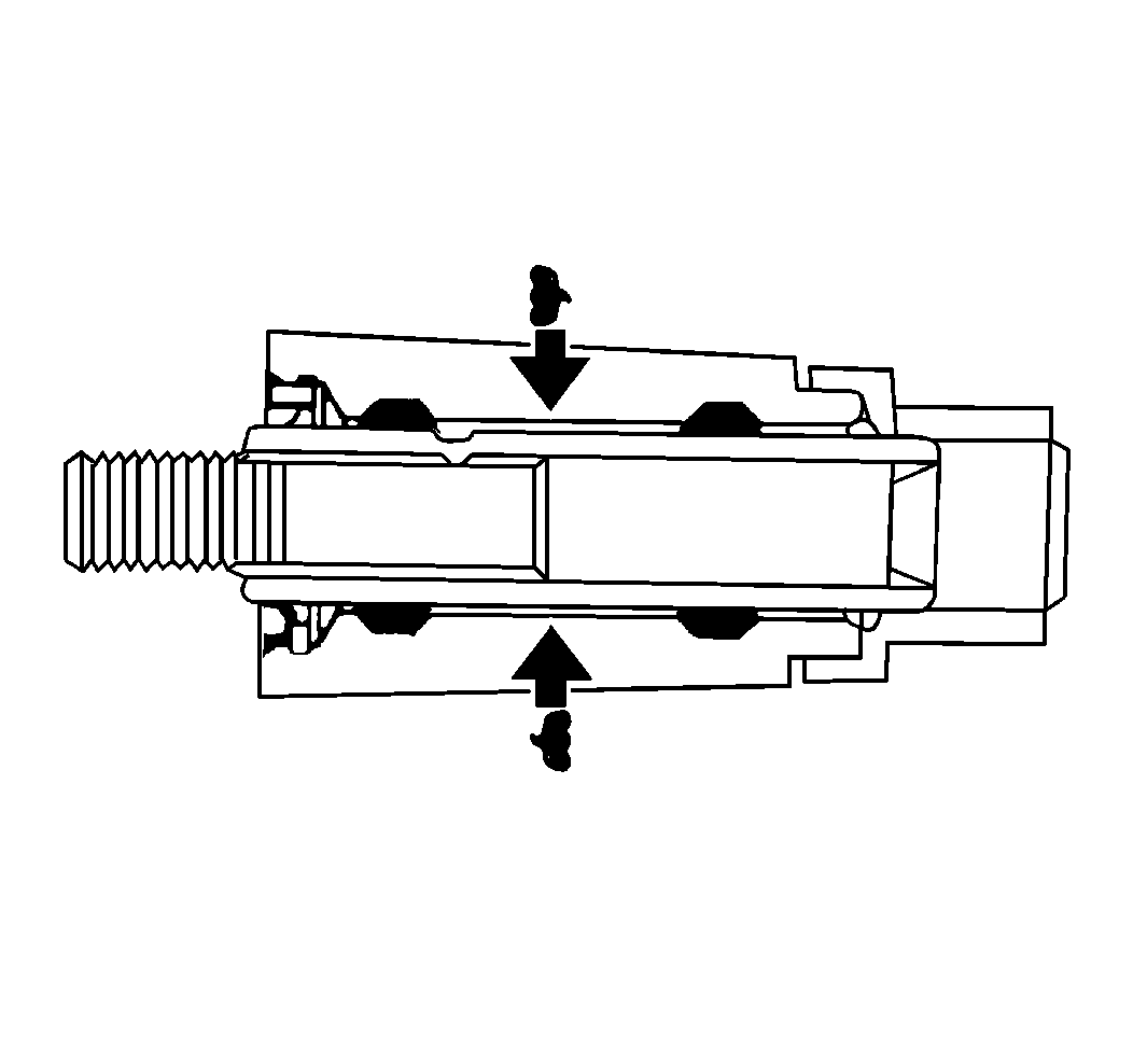
- Lubricate the sleeves and the bushings with Delco Silicone Lube GM P/N 18010909 or the equivalent.
- Install the bushings.
- Install the sleeves (RWD).
- Install the brake pads. Refer to Brake Pads Replacement .
- Install the caliper assembly.
- Install the mounting bolts.
- Install the brake hose to the caliper.
- Measure the clearance between the caliper and the steering knuckle.
- Install the tire and wheel. Refer to Wheel Installation in Tires and Wheels.
- Lower the vehicle.
- Bleed the brake system. Refer to Hydraulic Brake System Bleeding in Hydraulic Brakes.


Notice: Use the correct fastener in the correct location. Replacement fasteners must be the correct part number for that application. Fasteners requiring replacement or fasteners requiring the use of thread locking compound or sealant are identified in the service procedure. Do not use paints, lubricants, or corrosion inhibitors on fasteners or fastener joint surfaces unless specified. These coatings affect fastener torque and joint clamping force and may damage the fastener. Use the correct tightening sequence and specifications when installing fasteners in order to avoid damage to parts and systems.
Tighten
Tighten the bolts to 51 N·m (38 lb ft).
Tighten
Tighten the bolt to 44 N·m (32 lb ft).
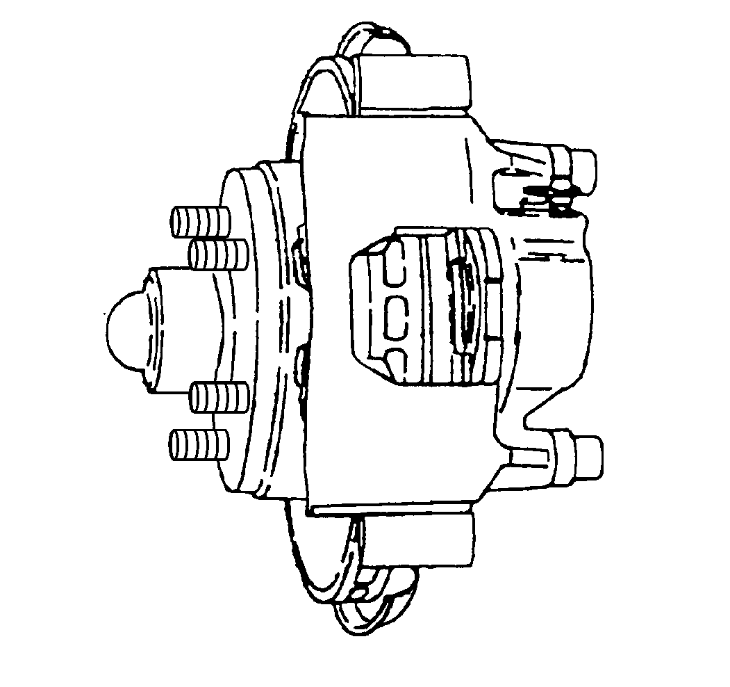
Measure the clearance at each end of the caliper individually and then add the measurements together.
Specification
The total should be 0.26-0.60 mm (0.010-0.024 in).
| • | If the total clearance between the caliper and the steering knuckle is less than 0.26-0.60 mm (0.010-0.024 in), file the steering knuckle equally on each side until the proper clearance is obtained. |
| • | If the total clearance between the caliper and the steering knuckle is more than 0.26-0.60 mm (0.010-0.024 in), inspect the brake caliper and the steering knuckle for damage and replace as needed. |
