Diagnosis will be much easier once you have identified a vibration as first-order of driveline rotation during the road test. Then identify the exact area that the vibration is coming from and take proper action.
In most cases, vibration may be reproduced in the stall. In the stall the vibration may be better or worse than that experienced during the road test.
The objective is to reduce the vibration to the lowest point possible in the stall, than evaluate the results on a road test. Many times, a vibration you were able to reduce drastically in the stall will be completely eliminated on the road.
The cause of first-order drive line vibration is usually excessive runout or an imbalanced component.
The following procedure offers a systematic process of elimination in order to determine which component is at fault:
- Raise the vehicle to curb height. Support the vehicle on a hoist or heavy stands. Refer to Lifting and Jacking the Vehicle in General Information.
- Remove the rear tire/wheel assemblies. Refer to Wheel Removal in Tires and Wheels.
- Remove the brake drums.
- Inspect the propeller shaft. The propeller shaft should be free of undercoating before continuing this diagnosis.
- Inspect the propeller shaft or U-joints for any obvious dents or damage. Dents or damage will contribute to first-order driveline vibrations.
- Start the engine.
- Place the transmission in gear.
- Run the vehicle up to the speed at which the vibration was most severe. Do not step on the brake while the brake drums are removed.
- Note the vibration present, and at what speed.
- If the vibration is not present, refer to Driveline Vibration Analysis (First-Order Driving Vibration Testing (Torque Sensitive)).
- If the vibration is present, determine which end of the driveshaft is vibrating the most. Hold your hand against the pinion nose and the transmission tailshaft, or hold an EVA vibration sensor up to each component.
- If the transmission tail is vibrating, touch the transmission crossmember under the transmission mount. If there is no vibration on the crossmember, then the transmission mount is working properly.
- Note which end of the driveshaft is the worst, and how severe the vibration is. The inspection will be a reference by which to judge future progress.
Helpful Hints
Do not fill the propeller shaft with foam, oil, or any other substance in order to correct a vibration. Filling the propeller shaft is only effective in reducing an unrelated condition called Torsional Rattle. Filling the propeller shaft should only be done in strict adherence to the procedure outlined in corporate bulletins that address Torsional Rattle. Failure to follow the correct procedure will induce a vibration and/or affect the structural integrity of the propeller shaft. The propeller shaft will then have to be replaced.
Propeller Shaft Runout
A propeller shaft or pinion (companion) flange with excessive runout causes first-order driveline vibrations. Use the following procedure in order to measure runout of the propeller shaft (2). The tolerances are critical for smooth operation of the driveline.
| • | Remove excess corrosion of the propeller shaft surface before checking runout. Also inspect for damage and dents. Replace dented propeller shafts. Remove any undercoating from the propeller shaft before proceeding. |
| • | The measurement procedure that follows applies to all one-piece and two-piece propeller shaft assemblies. |
Measuring Propeller Shaft Runout
Tools Required
| • | J 8001 Dial Indicator Set |
| • | J 7872 Magnetic Base Indicator Set |
- Raise the vehicle on a suitable hoist. Refer to Lifting and Jacking the Vehicle in General Information.
- Allow the wheels to spin freely.
- Attach the J 8001 and the J 7872 to a smooth part of the vehicle underbody, close to the area where runout will be measured (3, 4, 5).
- Place the transmission in Neutral. Rotate the pinion flange or transmission yoke by hand while taking the measurements for runout. The propeller shaft will turn easier in one direction than in the other. Removing the wheels and drums will also help. Refer to Propeller Shaft Runout Specifications .
- Do not include fluctuations on the dial indicator due to welds or surface irregularities.
- If the runout exceeds the tolerances at one or more points, do the following:
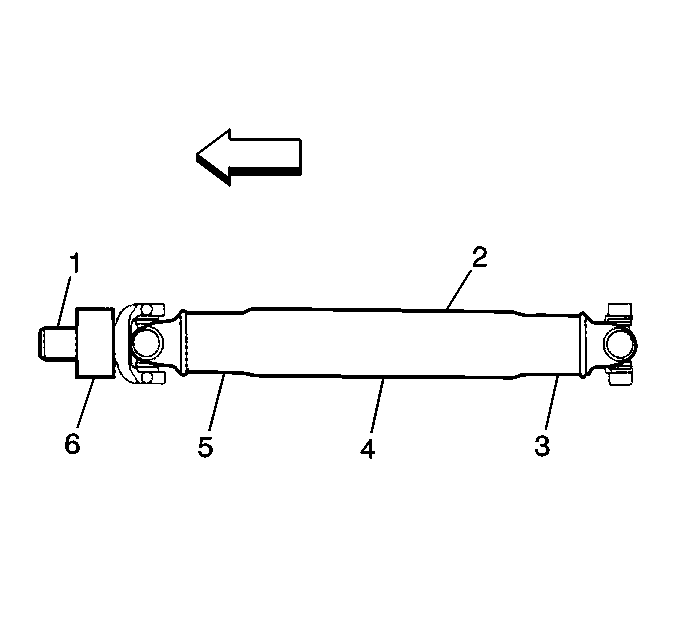
| 6.1. | Rotate the propeller shaft 180 degrees in the pinion flange. Reinstall the propeller shaft and recheck the measurement. |
| Important: When you replace a propeller shaft, check the new shaft for runout. Double-check the pinion flange runout if the replacement shaft runout is also out of tolerance. |
| 6.2. | If the runout still exceeds the tolerance, double-check the pinion flange runout before replacing the propeller shaft. Refer to Measuring Pinion Flange Runout. |
Measuring Pinion Flange Runout
Tools Required
| • | J 8001 Dial Indicator Set |
| • | J 23409 Dial Indicator Extension and Support |
| • | J 35819 Runout Gauge |
- Raise the vehicle on a hoist. Refer to Lifting and Jacking the Vehicle in General Information. Allow the wheels to rotate freely.
- Remove the propeller shaft from the pinion flange. Refer to Propeller Shaft Replacement in Propeller Shaft.
- Install the J 35819 and the dial indicator as shown.
- Rotate the pinion shaft 360 degrees and zero the dial indicator on the low spot.
- Rotate the pinion flange again and record the total runout.
- If the pinion flange runout is 0.15 mm (0.006 in) or less, remove the pinion flange balance weight.
- If the pinion flange runout is over 0.15 mm (0.006 in) but no less than 0.38 mm (0.015 in), and the runout compensation weight is at or near the low point of the pinion flange runout indicator reading, then no further action is necessary.
- If the pinion flange runout is more than 0.28 mm (0.011 in) but no greater than 0.38 mm (0.015 in), and the balance weight is not at or near the low point, then remove the weight. Re-index the pinion flange until the runout is 0.25 mm (0.010 in) or less.
- Replace the pinion flange if the runout cannot be 0.25 mm (0.010 in) or less. Then, recheck the runout. Service replacement flanges do not have balance weights and no weights should be added.
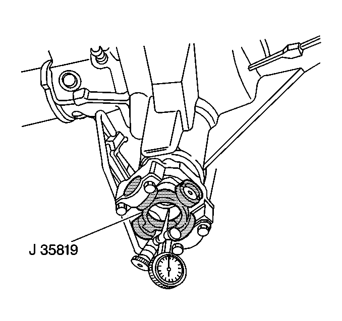
Important: The dial indicator will have inverted readings. You are measuring the inside diameter of the flange, and not the outside diameter. The highest reading on the dial indicator is the low spot. The lowest reading is the high spot.
Helpful Hints
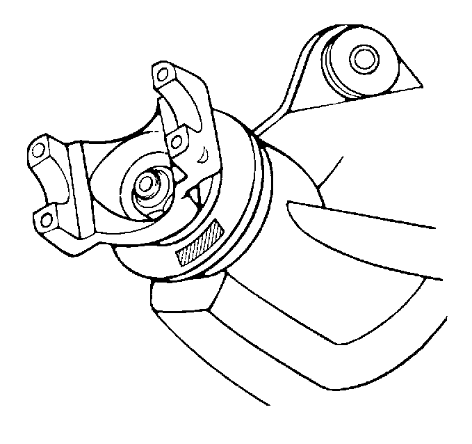
| • | If the J 35819 is unavailable, check the propeller shaft runout as near as possible to the flange. Rotate the shaft 180 degrees in the pinion flange, and reinstall the shaft. Recheck the measurement at the same location. A large difference in runout, 0.381 mm (0.015 in) or more, may indicate that the flange is out of tolerance. The flange is probably correct if the runout does not change at all. |
| • |
|
| • |
| • |
| • |
Correcting Vibration at the Pinion Nose
Most first-order driveline vibrations originate at the pinion nose end of the driveshaft. Ensure that the vibrations are at a minimum at this location in order to achieve acceptable results. Reduce the runout of the components to a minimum. Balance the driveline as a system when necessary.
- Measure the runout of the propeller shaft and check the tolerance.
- If the tolerance is excessive, mark the position of the shaft for future reference and rotate the shaft 180 degrees.
- Reinstall the shaft and recheck the runout. Inspect the level of vibration in order to determine if the vibration is lower or corrected.
- If the runout is still excessive, or if the vibration is still present, refer to Measuring Pinion Flange Runout. Replace the pinion flange or re-index the flange 180 degrees if the pinion flange runout exceeds the tolerance.
- Recheck the propeller shaft runout if the vibration is present after the pinion flange runout is corrected. If the propeller shaft runout is still excessive, correct the runout before doing a driveline system balance. Either replace the shaft with a shaft that is within tolerance or sublet the shaft to a reputable independent for straightening and re-balance. Ensure that the new or rebuilt shaft is within runout tolerance before you continue.
- Once the propeller shaft and pinion flange are within runout tolerances, check if the vibration is gone. If the level of the vibration is still unacceptable, perform a driveline system balance procedure.
Remove and reinstall the pinion flange only once on axles utilizing a crush type sleeve. Replace the sleeve with a new sleeve if the sleeve is crushed. Removing the sleeve requires removal of the ring and pinion set. Therefore, replace flanges with excessive runout. Regardless of the method used, measure the pinion flange runout in order to ensure that the flange is within tolerance.
Correcting Vibration at the Transmission Tailshaft
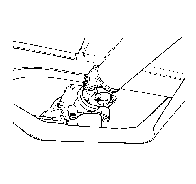
First-order driveline vibrations that originate at the transmission end of the propeller shaft are rare. If the tailshaft of the transmission is vibrating, inspect the tailshaft housing bushing for wear or damage. A leaky transmission tailshaft oil seal indicates bushing problems.
Feel for vibration at the crossmember underneath the transmission mount. If there is no vibration, the transmission mount is doing its job of isolating the vibration from the structure of the vehicle. The transmission mount is therefore probably not cause of vibration.
Use the following procedure if you can feel vibration on the crossmember and the tailshaft bushing, and if transmission output is normal:
- Measure the propeller shaft runout. If the runout is excessive, replace the shaft with one that has acceptable runout. Alternatively, sublet the shaft to a reputable independent service shop in order to have the shaft rebalanced and the runout corrected.
- Test drive the vehicle. If the vibration is still unacceptable, balance the shaft on the vehicle. Refer to Driveline System Balance with the Electronic Vibration Analyzer (EVA) or Driveline System Balance without the Electronic Vibration Analyzer (EVA).
Driveline System Balance with Electronic Vibration Analyzer (EVA)
To pinpoint the source, you must reproduce the vibration in the service stall and then determine which component is vibrating the most using the EVA:
- Support the vehicle on a suitable hoist or on safety stands. Ensure that the rear of the rear axle is at curb height. Do not allow the axle to hang. Refer to Lifting and Jacking the Vehicle in General Information.
- Remove the rear tire/wheel assemblies. Refer to Wheel Removal in Tires and Wheels.
- Remove the brake drums.
- Ensure that the propeller shaft is free of undercoating. Check for dents or damage to the propeller shaft or U-joints.
- Start the engine. Place the transmission in gear and run at the vehicle speed at which the vibration occurs at.
Caution: Never run the vehicle faster than 112 km/h (70 mph) when performing propeller shaft vibration or checking for balance. Stay clear of rotating components and balance weights to avoid personal injury. Do not run the vehicle on the hoist for extended periods of time to avoid engine or transmission overheating. Do not step on the brake pedal with the brake drums removed.
Determine which end of the propeller shaft is vibrating the most. Hold the EVA sensor against the pinion nose and the transmission tailshaft assembly. The higher the amplitude reading, the greater the vibration.
If the transmission tailshaft vibrates, check the transmission crossmember under the transmission mount. The vibration should not be present if the mount is doing its job.
Runout and Balance Testing with the Electronic Vibration Analyzer (EVA)
Ensure that the runout of the various driveline components are within specifications. If the runouts are within specifications, strobe balance the driveline. The EVA is able to simplify the balancing process, using the following procedure:
- Use the EVA in order to determine which end of the propeller shaft has the most vibration.
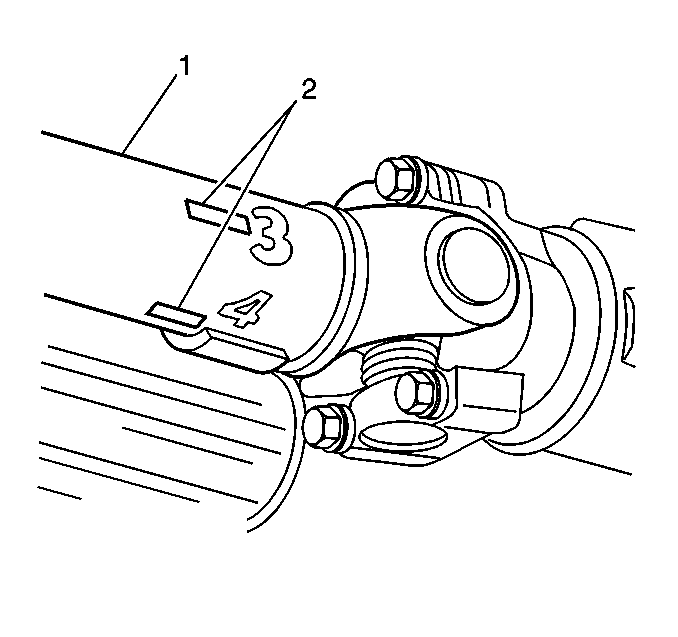
- Mark the end of the propeller shaft (1) that has the most vibration at four points (2), 90 degrees apart. Number the marks 1 through 4.
- Mount the EVA sensor onto the bottom of the following components:
- Start the engine.
- Turn OFF all engine accessories.
- Place the transmission in gear.
- Run the vehicle at the speed which causes the most vibration in the propeller shaft.
- Hook the timing light clip to the trigger wire.
- Plug the vibration sensor into Input A of the EVA. Input B does not have strobe light capability.
- Verify that the predominant frequency on the EVA display matches the frequency of the original vibration. Use the strobe light only if the rotation speed of the propeller shaft is the predominant frequency.
- The EVA displays a series of questions in order to select the correct filter. Press YES in order to select the desired filter. Ensure that the frequency is in the middle of the filter range. Use the full range only as a last resort.
- The display shows the test frequency, the amplitude and the filter range. The driveline is balanced when the amplitude is near two. In some cases a slightly higher amplitude will provide adequate balance.
- Point the timing light at the propeller shaft. The strobe effect will appear to freeze the propeller shaft. Note which of the numbered marks is at the bottom of the propeller shaft, or the 6 o'clock position. This position is the light spot.
- Turn the engine OFF.
- Install a weight directly on the light spot.
- Start the engine.
- Run the vehicle at peak vibration speed.
- Strobe the propeller shaft again.
| • | The differential housing |
| • | The transmission tailshaft assembly |
| • | Position the sensor as close to the propeller shaft as possible. Ensure that the UP side of the sensor faces up. Ensure that the sensor is horizontal. |
Notice: Do not use cruise control to maintain vehicle speed.
The propeller shaft is balanced if the strobe image is erratic and the amplitude is near two.
The propeller shaft is not balanced if one of the following conditions exist:
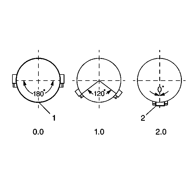
| • | The weight and the original light spot are at the 6 o'clock position (2). |
| The above condition means that there is not enough weight on the propeller shaft. In order to correct the balance, add a second weight next to the first weight. Inspect the balance again using the strobe light. |
| If the weights are now between 90 and 180 degrees off (between the 9 and the 3 o'clock positions) too much weight exists. In order to correct the balance, split the two weights equally on either side of the original light spot in order to produce a total weight between one and two weights (between 0 and 120 degrees apart). Inspect the balance again using the strobe light. Adjust the weights as necessary. |
| • | The weight and original light spot are 90 to 180 degrees off (between the 9 and the 3 o'clock positions) (1). |
| The above condition means that one weight is too much. In order to correct the balance, split the two weights equally on either side of the original light spot in order to produce a total weight less than one (between 120 and 180 degrees apart). Inspect the balance again using the strobe light. Adjust the weights as necessary. |
| • | The weight and the original light spot are within 180 degrees of the 6 o'clock position. |
| Move weight towards the 6 o'clock position. Inspect the balance again using the strobe light. Adjust the weight as necessary. Refer to the previous two conditions. |
If the shaft will not balance using two weights, then place a third weight on the light spot. Split the first two weights in order to produce a total weight between two and three weights.
If three weights fail to balance the driveline, then replace the propeller shaft.
When the propeller shaft balances, road test the vehicle in order to verify that the vibration is eliminated.
Driveline System Balance without the Electronic Vibration Analyzer
The following procedure is designed to fine-tune the balance of the propeller shaft while it is mounted in the vehicle. The procedure also is able correct residual imbalance of the remaining driveline components.
Prior to balancing the driveline system, verify that the propeller shaft and the pinion flange runout are within specification.
Do not overheat the engine when performing this procedure.
- Raise the vehicle to curb height. Support the vehicle on a hoist or on safety stands. Do not allow the axle to hang. Refer to Lifting and Jacking the Vehicle in General Information.
- Remove the rear tire/wheel assemblies. Refer to Wheel Removal in Tires and Wheels.
- Remove the brake drums.
- Determine which end of the propeller shaft has the most vibration in order to identify where to begin installing the hose clamps.
- Mark the end of the propeller shaft (1) which has the most vibration at four points, 90 degrees apart (2). Number the marks 1 through 4.

Troubleshooting Hints
The following procedure uses a trial and error method of determining where to place the hose clamps on the shaft. Use the following tips in order to help locate the clamps:
- Because the imbalance may be related to propeller shaft runout, begin installing the clamps at the low point of the propeller shaft runout.
- When the plant workers balance the propeller shaft, they use weights in graduated increments: 1/6 oz, 1/8 oz, etc. If the stock weight is too light or too heavy, place the hose clamp either directly in line with or opposite to the stock weight.
The last method involves road testing the vehicle at a speed which the vibration is felt.
- Carefully hold a piece of chalk up to the very end of the propeller shaft. Barely touch the chalk to the shaft.
- Shut the engine OFF in order to stop the propeller shaft from rotating. Do not step on the brake pedal. Do not put the transmission in PARK.
- Inspect the chalk mark.
If you performed the above procedure correctly, the chalk mark will indicate the heavy spot on the shaft. The heavy spot deflected downward and touched the chalk. If the chalk mark circle the entire shaft, touch the chalk more gently to the shaft. Ensure that the chalk touches only the heavy spot. Once the heavy spot is located, place the hose clamp 180 degrees opposite to the chalk mark. Then perform the following steps:
- Place the hose clamp at the light spot, or at any of the four points marked previously.
- Test drive the vehicle at the speed at which the vibration occurred. Record any changes in the vibration.
- Move the clamp to the other positions.
- Test drive the vehicle each time the clamp is moved. Record any changes in vibration. Note which position gives the best balance.

If the vibration does not change at all, or gets worse, then one clamp is too light or too heavy.
| • | If the vibration did not change at all, then repeat the procedure using two clamps together. |
| • | If the vibration got worse, repeat the procedure using two clamps separated. Separate the clamps to reduce the spinning weight. |
Continue the trial and error procedure using different weights in different locations until you achieve the best balance. If more that three clamps aligned in the same position are required, then replace the propeller shaft.
If you are able to reduce the vibration in the stall, but are unable to eliminate the vibration completely, perform a road test on the vehicle. A slight vibration noticeable in the stall may not be noticeable on the road.
Propeller Shaft Balance Weights
Use the following phasing procedure with two hose clamps in order to accurately place any required amount between zero weights (0.0 total weight) to two weights (2.0 total weight).
| • |

|
| • |
| • |
Driveline Working Angles
Tools Required
| • | J 38460 Digital Inclinometer |
| • | J 23498-A Bubble Inclinometer |
| • | J 23498-20 Adapter |
The objective of this section is to correct the conditions that interfere with the proper cancellation effect of the U-joints. The most common condition, especially where the where launch shudder is concerned, is incorrect driveline working angles. However, other factors may aggravate the condition.
Address these factors before you attempt to measure or correct driveline working angles:
| • | Worn, failed, damaged, or improperly installed U-joints |
| • | Worn, collapsed, or improper powertrain mounts |
| • | Incorrect vehicle trim height adjustment for the front suspension. This condition aggravates launch shudder. |
| • | Incorrect trim height adjustment for the rear suspension. |
| • | Trim height inspection includes trim heights that are too low or too high. Vehicles equipped with aftermarket lift kits, vehicles that are constantly loaded with cargo, and custom conversion vans all fit in this category. On rear drive vehicles, the pinion nose tilts upward as the rear trim height is lowered. |
If a second-order driveline vibration exists after these conditions are corrected, measure and correct the driveline angles.
If the complaint is present only with cargo in the vehicle, perform the measurements with the vehicle fully loaded. Once a second-order driveline vibration has been corrected with the vehicle loaded, the vibration may reappear with the vehicle unloaded. The reverse of this is also true. You may have to reach a compromise with the customer in this case.
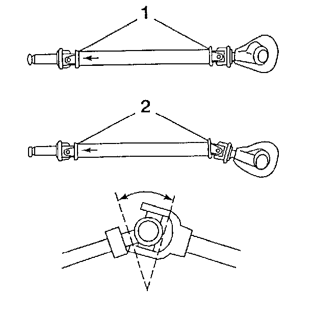
Driveline working angle does not refer to the angle of any one shaft (2), but to the angle that is formed by the intersection of two shafts (1), as shown.
The procedure for measuring and correcting driveline working angles depends on whether the vehicle is equipped with a one or two-piece propeller shaft.
You need a J 38460 or an equivalent tool to perform these measurements.
| • | The J 23498-A has a magnetic base for mounting on the joint bearing caps, along with a bubble level and angle scale for taking accurate measures. |
| • | The J 38460 display eliminates guesswork and is accurate to 1/10th of a degree. |
| • | Use the J 23498-20 for joints that are inaccessible. |
To verify the accuracy of the adapter, check the angle of an angle of an accessible joint with the inclinometer prior to assign it on an inaccessible joint.
Preliminary Checks
Raise the vehicle on a suitable hoist or on safety stands. Ensure that the rear axle is supported at curb height and that the wheels are free to spin. Refer to Lifting and Jacking the Vehicle in General Information. Place the transmission in NEUTRAL. Make sure the vehicle has a full tank of fuel or the equivalent amount of weight in the rear to simulate a full tank. 3.8 liters of gasoline (one gallon) weighs approximately 2.8 kg (6.2 lb).
Checking Phasing of U-joints
Inspect the propeller shaft for correct phasing. This means that the front and rear U-joints are directly in line or parallel with each other so that proper cancellation takes place.
- Rotate the propeller shaft so that the propeller shaft rear U-joint bearing cap (1) is vertical as shown.
- Ensure that the front bearing cap (1) is also vertical.
- Place the inclinometer on the propeller shaft rear U-joint bearing cap in order to ensure that both U-joints are vertical.
- Set the indicator line above the sight glass on 15 (the horizontal reference) and rotate the propeller shaft until the bubble centers in the sight glass. This brings the rear U-joint to vertical.
- Remove the inclinometer without disturbing the setting. Leave the setting on 15 and install the inclinometer on the front U-joint. The bubble should remain centered plus or minus 3 degrees if the shaft is properly phased.
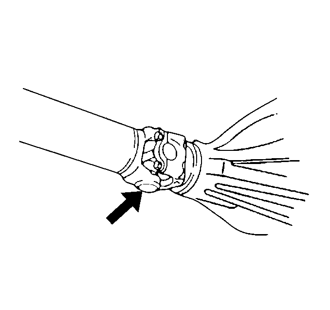
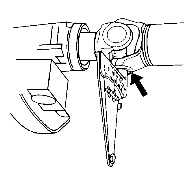
The out of phasing of the single-piece propeller shaft is very unusual. If the shaft is visibly out of place, the end yokes are welded on in the wrong position, or the shaft is damaged due to twisting. In either case, replace the propeller shaft before continuing with this procedure. Refer to Propeller Shaft Replacement in Propeller Shaft.
Measuring the Working Angles
The working angle of a U-joint is the difference between the angles formed when two shafts intersect. One piece propeller shaft systems have two working angles, the front and the rear.
| • | The two working angles should be equal within ½ of a degree. |
| • | The working angles themselves should not exceed 4 degrees. |
| • | The working angles themselves should not be equal to zero because a zero working angle will cause premature U-joint wear due to lack of rotation of the U-joints. |
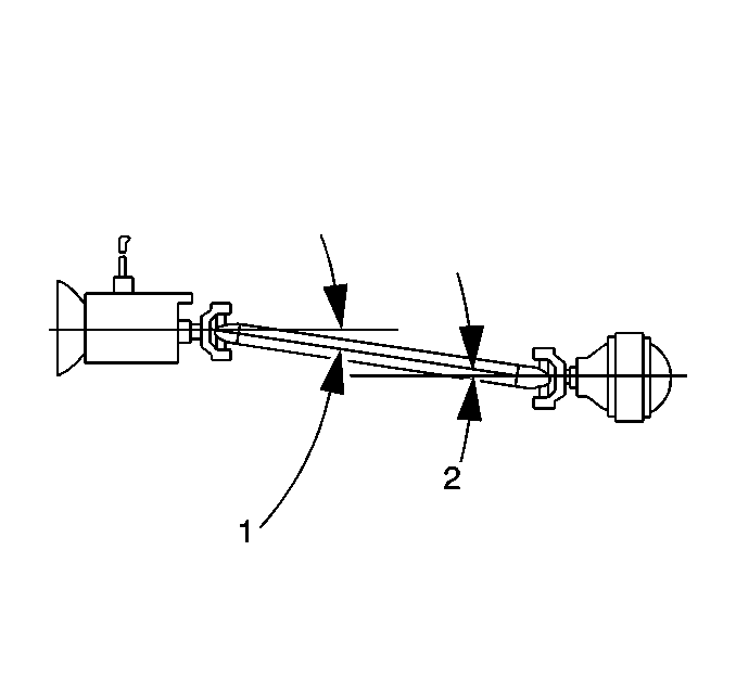
The angle of the propeller shaft and the rear axle pinion form the rear working angle (2). The angle of the propeller shaft and the transmission output shaft form the front working angle (1).
The angles of these components are most accurately measured from the U-joint bearing caps. The bearing caps should be free of corrosion or foreign material to ensure accurate readings. Remove any snap rings that may interfere with the correct placement of the inclinometer. Do not forget to reinstall them after you take the measurements.
Take the measurements from the same side of the propeller shaft to maintain consistent angle measurements (either driver or passenger side).
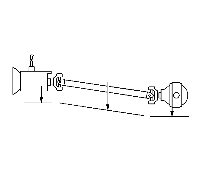
It is extremely helpful to record the readings on a diagram like the one shown as you proceed through the measurements.
Evaluation
The two working angles in a one-piece propeller shaft system should be equal to within ½ of a degree for effective cancellation.
Correcting Working Angles
In order to change the working angles, shim the components up or down. Look closely at the existing angles. Use the existing angles and the shims in order to achieve the correct working angles.
Compared to horizontal or true level, the components located at the rear of the vehicle are usually lower than the components located at the front of the vehicle. This condition is called down in the rear. If a component with a down in the rear angle is shimmed up at the rear, then the shim will bring the component closer to the horizontal (zero). Alternately, if a component with a down in the rear angle is shimmed down, then the component will move farther from the horizontal (zero).
Rear Axle Wind-Up
Rear axle wind-up may cause launch shudder even when all of the working angles are within specifications. Rear axle wind-up occurs when heavy torque during acceleration causes the pinion nose to point upward. In order to compensate for axle wind-up, tip the pinion nose downward. Install the axle shims incrementally, performing a road test after each shim. Add shims until the road test indicates that the shudder is eliminated.
Rear Axle Shims
Wedge shims of different sizes are available through GMSPO and independent suppliers for the purpose of shimming the rear axle angle. GM shims are available in two, three and four degrees.
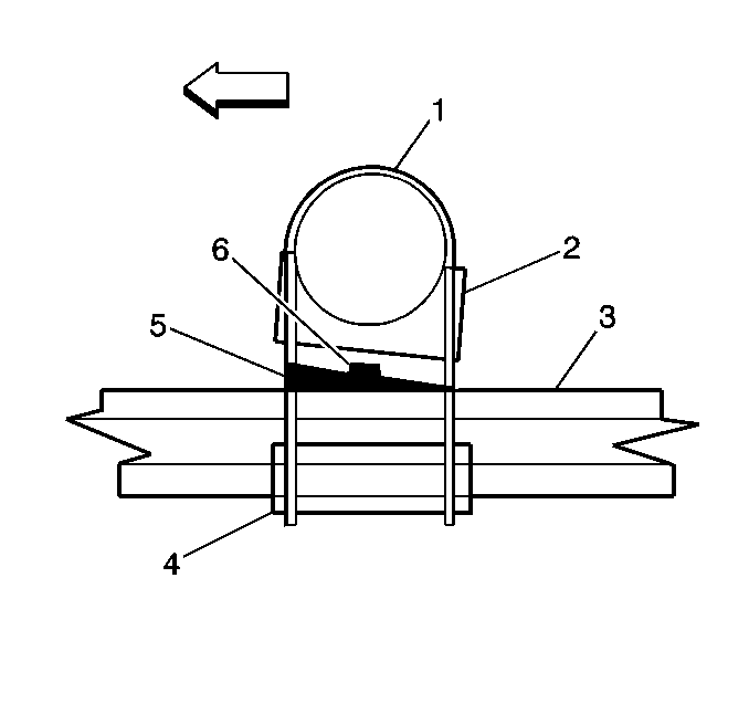
Caution: Never attempt to shim a rear axle using anything except shims that are designed for this purpose. Failure to do so will result in the shims falling out and a loss of vehicle control and that could cause personal injury.
Install the shims (5) in order to increase or decrease the angle of the rear axle pinion. Install the shims between the leaf spring (3) and the spring seat (2). Depending on the design of the suspension (leaf spring on top or underneath the axle), and the direction of the desired change, install the shims with either the thick side toward the front of the vehicle or toward the rear of the vehicle.
Important: After installing the shims, ensure that the U-bolt has two or three threads above the nut. Ensure also that the center bolt, located in the spring seat, is long enough to seat in the locator hole. If these two conditions do not exist, use longer U-bolts and center bolts. Longer U-bolts and center bolts are available through local spring shops.
Transmission Shims
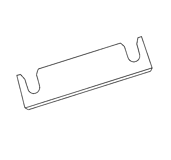
If a transmission requires shims, order the shims through GMSPO.
Installing most shims will change the transmission angle approximately ½ degree.
When shimming transmissions, use a shim made from steel stock at the necessary thickness. Ensure that the shim contacts the full width of the area to be shimmed. Do not use washers.
Front Drive Axle Vibrations
Four-Wheel Drive vehicles have an additional drive axle to move the vehicle. The four-wheel drive system transfers power from the transmission through the transfer case and the front propeller shaft to the front drive axle. The front drive axle then splits the power to the left and right front wheel drive shafts. The left side connects directly to the wheel drive shaft, the right side uses an inner axle to connect to the right wheel drive shaft. Similar in design to a front-wheel drive (FWD) wheel drive shaft, the drive shaft use tri-pod and constant-velocity (CV) joints to transfer power to the front wheels.
Although the front drive axle components are balanced during assembly, certain problem conditions may occur and require diagnosis and correction. These conditions are:
| • | Launch Shudder |
| • | Third-Order Tire-Related Vibrations |
| • | Growing (Wheel Bearing) Noise |
| • | Clicking Noise or Shudder During Turns |
Launch Shudder
Launch shudder is typically a shaking sensation that is felt in the steering wheel and/or the front of the vehicle during moderate to heavy acceleration from a standing start. Launch shudder might also be described by a customer as a rocking back-and-forth motion in the vehicle during acceleration.
Launch shudder can be caused by worn or damaged inner Tri-pod joints and also by excessive inner joint angularity. Excessive joint angles are the result of a front trim or spring height that is set too high. A damaged or misaligned front differential carrier bushing can also crate excessive joint angles and cause launch shudder.
When the vehicle is in four-wheel drive, heavy acceleration can cause the front suspension rise from the high torque of the vehicle's powertrain. When the suspension height rises, the inner Tri-pod joint angles increase and can cause a lunch shudder condition, if the joints are worn or if the angles are already excessive before acceleration.
Because the inner Tri-pod joint is usually the cause of launch shudder, the disturbance will typically be related to third-order tire rotation frequency. For diagnosing the complaint, use the EVA in the Snapshot Mode or use a reed tachometer.
Once the type of disturbance has been identified, visually inspect the drive axles for worn or damaged inner joints. If no obvious problem is detected, measure the trim height to determine if the suspension is causing an excessive joint angle. Refer to Trim Height in Suspension General Diagnosis. Do not measure the body height. Body height measurements are not used, because potential sheet metal variations could lead to mis-diagnosis of the problem cause.
Caution: Road test a vehicle under safe conditions and while obeying all traffic laws. Do not attempt any maneuvers that could jeopardize vehicle control. Failure to adhere to these precautions could lead to serious personal injury and vehicle damage.
If the trim height is out-of-specification, check for a sagging or broken torsion bar. Adjust or replace the torsion bar. Refer to Torsion Bar Replacement in Front Suspension.
Third-Order Tire-Related Vibrations
Although worn or damaged inner Tri-pod joints can cause launch shudder, they may also cause vehicle speed-related third-order tire vibrations.
Tri-pod joints are so named because of their design characteristics. Tri-pod or Tri-podial joints have three trunnions (or a trilobal spider assembly) that fit into a race or cup. The assembly is allowed to move in and out freely to compensate for drive axle length changes during suspension travel.
Third-order tire-related disturbance can occur if the joint becomes worn or damaged and has excessive free-play or lash. The worn joint will create three disturbances per one revolution on the axle shaft. Because the axle shaft turns at the same rate as the wheel, third-order tire-related vibrations will result. For CV and Tri-pod joint replacement or repair, refer to Wheel Drive Shaft Inner Joint and Boot Replacement or Wheel Drive Shaft Outer Joint and Boot Replacement in Wheel Drive Shafts.
Growling (Wheel Bearing) Noise
Four-Wheel Drive hub and bearing assemblies can make a low, growling noise that increases with vehicle speed. Tires and bearings can make a similar noise and both are vehicle-speed-sensitive.
To differentiate between tire noise and bearing noise, drive the vehicle in a straight line and perform several turning maneuverers side-to-side. A worn wheel bearing will typically exhibit increased noise during turns. If the noise level increases during a right-hand turn, then the left-hand wheel bearing will generally be causing the problem. The opposite is true for a left-hand turn. If a bearing and not the tires is the cause of the disturbance, the noise level increases when turning because an added load is applied to the bearing at fault. If a wheel bearing needs to be replaced, refer to Front Wheel Hub, Bearing, and Seal Replacement in Front Suspension.
Clicking Noise or Shudder During Turns
A clicking noise or shudder during vehicle turns is usually a symptom caused by a worn or damaged outer or outboard constant-velocity (CV) joint.
During a visual inspection of the drive axle, look for a damaged boot on the outer CV joint. A damaged boot can allow water and other contaminants such as dust and dirt to compromise lubrication and prematurely destroy the joint. The CV joint will no longer function smoothly, causing the disturbance. For CV joint replacement, refer to Wheel Drive Shaft Inner Joint and Boot Replacement or Wheel Drive Shaft Outer Joint and Boot Replacement in Wheel Drive Shafts.
