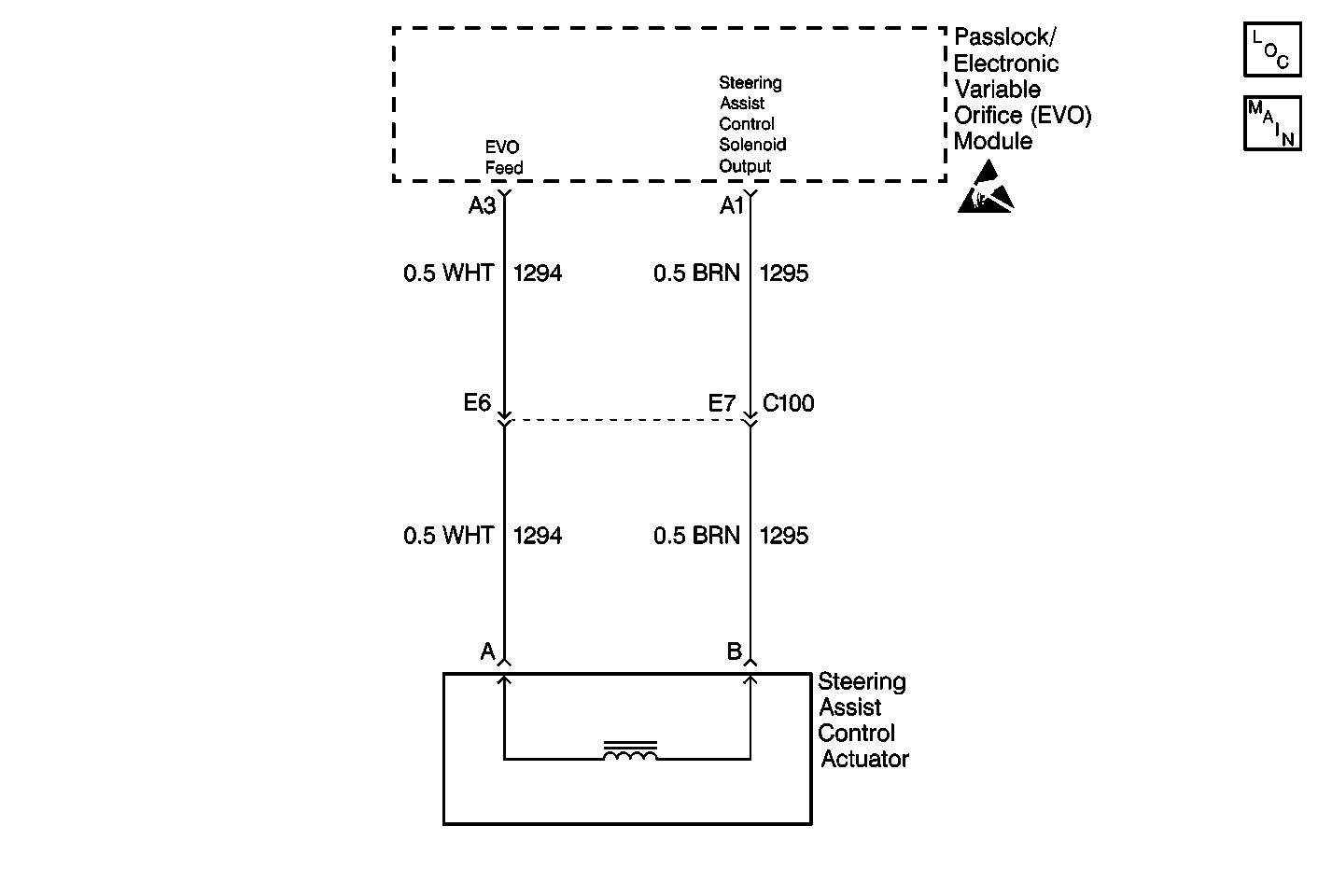
DTC C0498

Circuit Description
The electronic variable orifice (EVO)/Passlock™ module supplies a 0-850 milliamperes percentage duty cycle current to the steering assist control solenoid. The current extends or retracts the actuator valve inside the solenoid. The extension or retraction will regulate an orifice on the power steering pump. The regulated orifice will cause the fluid flow output to modulate. The fluid flow output will increase or decrease in steering wheel effort. Supplying a 0 milliampere to the steering valve control solenoid will fully retrace the valve. This provides the maximum fluid flow and power steering assist. Suppling 850 milliamperes to the steering assist control solenoid extends the valve. The extended valve will decrease the fluid flow and minimize the power steering assist. The EVO/Passlock™ module constantly adjusts the current flow to the steering assist control solenoid based on the vehicle speed and the steering wheel position. The adjusting current flow provides vehicle speed related power steering assist.
Conditions for Setting the DTC
There is an open, or a short to ground, or a short to voltage in the following circuits while the EVO/Passlock™ module is pulsing the current to the steering assist control solenoid:
| • | CKT 1294 (WHT) |
| • | CKT 1295 (BRN) |
The following conditions are necessary for setting the DTC:
- The voltage is below 0 volts.
- The voltage is at the battery voltage.
- The conditions must be met for 1 second or longer.
Action Taken When the DTC Sets
The EVO/Passlock™ module will not send any current to the steering assist control solenoid. This will cause the solenoid valve to retract. The retracting valve will provide the maximum fluid flow and full power steering assist at all time.
Conditions for Clearing the MIL/DTC
| • | A history DTC will clear after 100 consecutive ignition cycles occur without a fault. |
| • | Use a scan tool in order to clear the history and the current DTC(s). |
Diagnostic Aids
Perform the following code tests first if DTC C0498, DTC C0499, DTC C0502 or DTC C0503 are present:
| • | The following conditions may cause an intermittent problem: |
| • | A poor connection. |
| • | A break in the wire insulation that exposes the internal wire. |
| • | A wire that is broken on the inside of the insulation. |
| • | Thoroughly check the EVO/Passlock™ module and the vehicle control module (VCM) for the following conditions: |
| • | Backed out terminals |
| • | Broken locks |
| • | Improperly formed terminals |
| • | Damaged terminals |
| • | Weak terminal retaining tension |
| • | Proper routing |
| • | The solenoid valve may be stuck. The stuck valve provides uncalculated power steering assist. |
| Refer to Power Steering System Test in Power Steering System. |
Test Description
The number(s) below refer to the step number(s) on the diagnostic table.
-
This step ensures that you perform the Diagnostic System Check.
-
This step check for a short to voltage in CKT 1294 (WHT) or CKT 1295 (BRN) with the EVO/Passlock™ module disconnected.
-
This step checks for the commanded and the actual duty cycle.
-
This step check the steering assist control solenoid harness for a short to voltage with the solenoid disconnected on CKT 1294 (WHT) and CKT 1295 (BRN).
-
This step checks the steering assist control solenoid harness for a short to ground. This steps check for an open with the solenoid disconnected on CKT 1294 (WHT) and CKT 1295 (BRN).
If voltage is indicated, there is a short to voltage on CKT 1294 (WHT) or CKT 1295 (BRN).
If the voltage is 0, there is a short to ground on CKT 1294 (WHT) or CKT 1295 (BRN).
Step | Action | Value(s) | Yes | No | ||||||||||
|---|---|---|---|---|---|---|---|---|---|---|---|---|---|---|
Did you perform the Diagnostic System Check? | -- | Go to Step 2 | Go to the Diagnostic System Check | |||||||||||
Did you find any DTC(s)? | -- | Go to Step 3 | ||||||||||||
Are the values equal? | -- | Go to the Diagnostic System Check | Go to Step 4 | |||||||||||
Is there voltage present? | -- | Go to Step 5 | Go to Step 6 | |||||||||||
5 | Repair the short to voltage in CKT 1294 (WHT) or CKT 1295 (BRN) between the EVO/Passlock™ module and the steering assist control solenoid. Is the repair complete? | -- | Go to the Diagnostic System Check | Go to Step 6 | ||||||||||
Is any voltage present? | -- | Go to Step 7 | Go to Step 8 | |||||||||||
7 | Repair the short to ground in CKT 1294 (WHT) or CKT 1295 (BRN) between the EVO/Passlock™ module and the steering assist control solenoid. Is the repair complete? | -- | Go to Step 9 | -- | ||||||||||
8 | The problem is intermittent. Refer to Intermittents and Poor Connections Diagnosis in Wiring Repair. Did you perform the intermittent diagnosis? | -- | -- | -- | ||||||||||
9 |
Is the repair complete? | -- | Go to Diagnostic Aids | -- |
