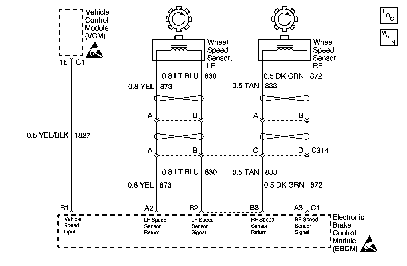
Circuit Description
The EBCM receives the rear wheel speed signal from the Vehicle Control Module (VCM). The rear wheel speed signal originates from the Vehicle Speed Sensor (VSS) which is connected to the VCM. When the vehicle is not moving, the VCM will have 12 VDC present on the circuit. The EBCM checks for this voltage when the vehicle is not moving.
Conditions for Running the DTC
| • | Ignition switch in the RUN position. |
| • | All wheel speed sensor signals above 32 km/h (20 mph) with brake applied, or 19 km/h (12 mph) with brake released. |
Conditions for Setting the DTC
| • | Sudden loss of front wheel speed sensor signal 10 to 15 miliseconds. |
| • | Sudden increase in rear wheel speed sensor signal for 105 miliseconds. |
Action Taken When the DTC Sets
| • | The ABS indicator lamp turns on |
| • | The ABS disables |
Malfunction responses to DTC C0237 vary, depending on the affected subsystem.
| • | ABS--Condition latched |
| • | DRP--DRP critical |
For a detailed explanation of DTC malfunction responses, refer to Self-Diagnostics
Conditions for Clearing the DTC
| • | Repair the conditions responsible for setting the DTC |
| • | Use the Scan Tool Clear DTCs function |
| • | Both a Condition Latched or Ignition Latched DTC may exist momentarily, or constantly. In either of the cases, the DTC will be stored in the EBCM memory until it is repaired, and/or the DTC is cleared. After the DTC is repaired and/or cleared and the ignition is turned to ON, the ABS lamp will remain lit until the EBCM completes a power-up self test. This test concludes when the vehicle has reached a speed of greater than 13 km/h (8 mph) and the wheel speed inputs have been checked by the EBCM. |
Diagnostic Aids
Correct any DTCs that are set in the VCM first.
This DTC can be set by a malfunction in the VSS, or a fault in CKT 821, 822 or 1827.
In addition, any of the following conditions may cause an intermittent malfunction:
| • | A poor connection |
| • | Wire insulation that is rubbed through |
| • | Wire breaks inside the insulation |
Thoroughly check any circuitry that is suspected of causing the intermittent complaint for the following conditions:
| • | Backed out terminals |
| • | Improper mating |
| • | Broken locks |
| • | Improperly formed or damaged terminals |
| • | Poor terminal to wiring connections |
| • | Physical damage to the wiring harness |
Test Description
The numbers below refer to the steps in the diagnostic table:
-
This step uses the voltage output from the VCM to check the 1827 CKT.
-
This step attempts to determine if there the VCM can process the VSS input and deliver a VSS output on CKT 1827.
Step | Action | Value(s) | Yes | No |
|---|---|---|---|---|
1 | Did you perform the ABS Diagnostic System Check? | -- | Go to Step 2 | Go to Diagnostic System Check |
2 | Using the scan tool, check for any powertrain DTCs Does the scan tool indicate any powertrain DTCs? | -- | Go to Powertrain On Board Diagnostic (OBD) System Check - Automatic Transmission | Go to Step 3 |
Does the voltage measure greater than the specified value? | 10 volts | Go to Step 4 | Go to Step 5 | |
Does the voltage measure greater than the specified value? | 100 mv | Go to Step 7 | Go to Step 6 | |
5 | Test the vehicle speed sensor circuit for an open or short to ground. Refer to Circuit Testing and Wiring Repairs in Wiring Systems Did you find and correct the condition? | -- | Go to Step 9 | Go to Step 8 |
6 | Test the vehicle speed sensor circuit for a short to voltage. Refer to Circuit Testing and Wiring Repairs in Wiring Systems Did you find and correct the condition? | -- | Go to Step 9 | Go to Step 8 |
7 | Replace the EBCM. Refer to Electronic Brake Control Module Replacement . Did you complete the replacement? | -- | Go to Step 9 | -- |
8 | Replace the VCM. Refer to VCM Replacement/Programming in Engine Electrical. Did you complete the replacement? | -- | Go to Step 9 | -- |
9 | Operate the vehicle under the conditions for running the DTC as specified in the supporting text. Does the DTC set? | -- | Go to Step 2 | System OK |
