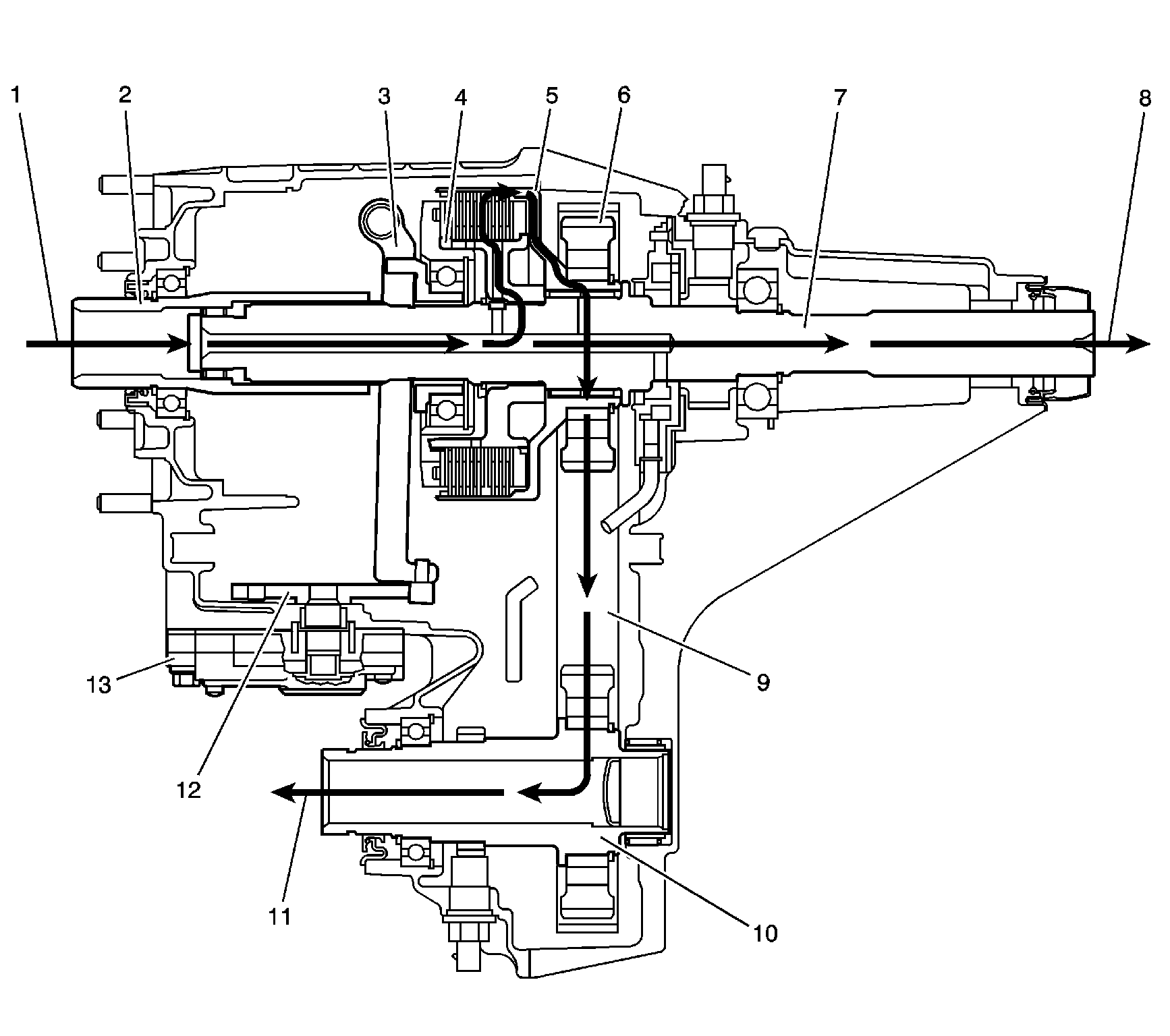
Auto 4WD Power Flow

Power is delivered from the transmission (1) to the input shaft (2). The input shaft (2) is splined to the rear output shaft (7). To deliver the power to the rear propeller shaft (9), the power is constant through the rear output shaft (7). When power is required for the front propeller shaft (11), a command is sent to the encoder motor (13). The encoder motor (13) rotates the shift detent lever (12), which is cam shaped. The cam action moves the clutch lever (3). The clutch lever (3) pivots on the clutch lever pivot studs, and moves toward the clutch apply plate to engage the clutch. As more pressure is applied to the clutch apply plate, the clutch discs are compressed. Using the inner clutch discs, which are engaged with the clutch hub (4), and the outer clutch discs, which are engaged with clutch housing (5), the power flow is delivered to the clutch housing (5). The clutch hub (4) is splined to the rear output shaft (7). The clutch housing (5) rotates on a needle bearing on the rear output shaft (7). The chain drive sprocket (6) is splined to the clutch housing (5). The power flows from the drive sprocket (6), through the chain (9), to the chain driven sprocket. The chain driven sprocket is splined to the front output shaft (10). The power flow is delivered to the front propshaft (11) through the front output shaft (10).
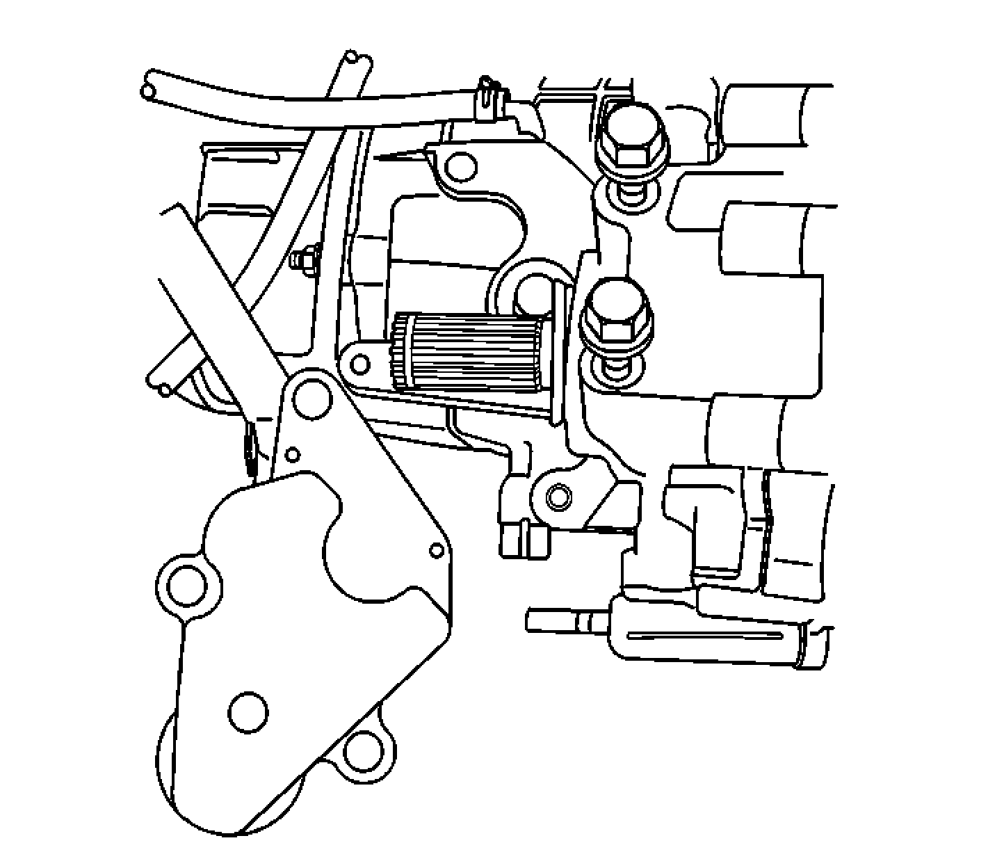
Some of the changes to the transfer case, that will take place over this model year, include the following:
| • | The oil pump suction pipe and screen will change to a one piece design. |
| • | The case half bolts will have a cup style washer and the bolt can be used again. |
| • | The clutch apply plate, clutch hub, and clutch oil restrictor plate will have a design change. |
New Venture Gear 136 Automatic Transfer Case
During normal driving situations, the Auto 4WD mode is active. During the Auto 4WD mode, the transfer case shift control module monitors rear wheel slip speed, based on the inputs from both the front and rear propshaft speed sensors. When the vehicle experiences a rear wheel slip condition, the transfer case shift control module sends a pulse width modulated (PWM) signal to an electronic motor, transfer case encoder motor. This motor rotates the transfer case sector shaft, applying a clutch pack. This clutch pack is designed to deliver a variable amount of torque, normally delivered to the rear wheels, and transfers it to the front wheels. Torque is then ramped up to the front wheels, until the front propshaft speed sensor matches that of the rear propshaft speed sensor. Torque is then ramped down, until torque is completely removed from the front wheels or until rear wheel slip is once again detected. The process then repeats.
Transfer Case Electrical Components
View the list of major components that make up the automatic transfer case (ATC) system below.
SERVICE Indicator (4WD/AWD) Lamp
The SERVICE indicator (4WD/AWD) lamp is an integral part of the cluster and cannot be serviced separately. This lamp is used to inform the driver of malfunctions within the automatic transfer case (ATC) system. The SERVICE indicator (4WD/AWD) lamp is controlled by the transfer case shift control module via a Class 2 message or by a Service Indicator Control circuit.
Transfer Case Encoder Motor

The transfer case encoder motor consists of a permanent magnet (PM) DC motor and gear reduction assembly. It is located on the left hand side of the transfer case. When activated, it turns the sector shaft of the transfer case to shift the transfer case and to apply the clutch that applies the front propshaft. The encoder motor is controlled with a pulse width modulated (PWM) circuit provided by the transfer case shift control module. This circuit consists of a power supply relay, Motor Control A, and supplies voltage to the motor. The Motor Control B circuit is a PWM driver that varies the duty cycle to control the amount of current through the motor to ground. The transfer case encoder motor can be turned ON and OFF using a scan tool. You may also monitor Motor Control A and B circuits using a scan tool.
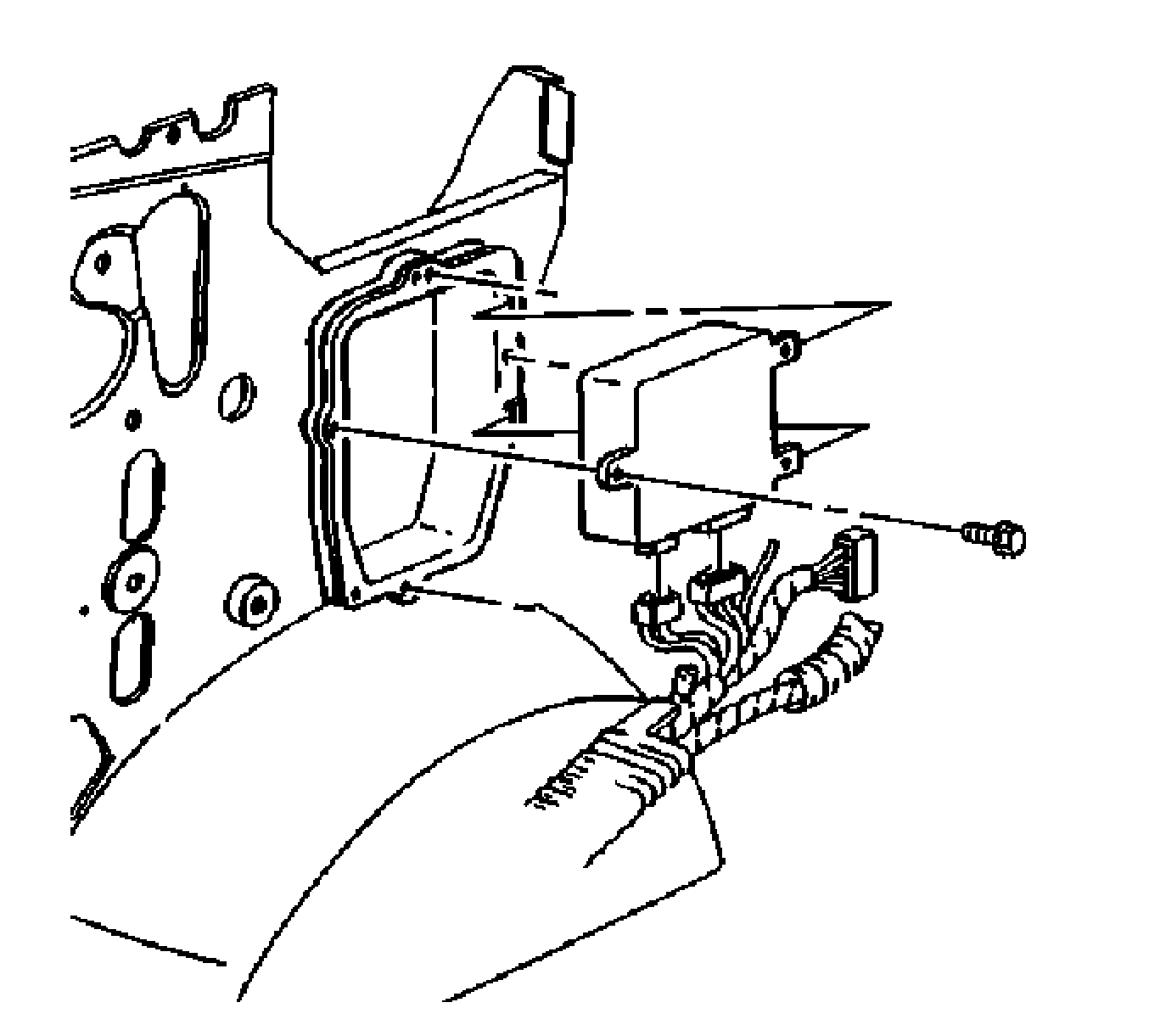
Transfer Case Shift Control Module

The transfer case shift control module uses the VIN information for calculations that are required for the different calibrations used based on axle ratio, transmission, tire size, and engine. The system does not know which calibration to use without this information. This information is provided to the transfer case shift control module via Class 2 data bus from the powertrain control module (PCM). The transfer case shift control module monitors front and rear propshaft speed as well as controlling the operation of the transfer case encoder motor assembly.
Transfer Case Speed Sensors
There are three speed sensors mounted on the transfer case. 2 speed sensors are mounted on the rear output shaft and one on the front output shaft. Each speed sensor is a permanent magnet (PM) generator. The PM generator produces an AC voltage. The AC voltage level and number of pulses increases as speed increases.
Front Propshaft Speed Sensor - The transfer case shift control module converts the pulsating AC voltage from the front transfer case speed sensor to front propshaft speed, in RPM to be used for calculations, and to monitor the difference between the front and rear sensor speed. It is also used in the AUTO 4WD mode to determine the amount of slip and the percent of torque to apply to the front axle. The front propshaft speed can be displayed with a scan tool.
Rear Propshaft Speed Sensor - The transfer case shift control module converts the pulsating AC voltage from the rear transfer case speed sensor to a rear propshaft speed, in RPM to be used for calculations. The rear propshaft speed can be displayed with a scan tool.
Vehicle Speed Sensor - One of the 2 speed sensors on the rear output shaft is the vehicle speed sensor (VSS) input to the powertrain control module (PCM). The PCM sends this information to the transfer case shift control module via the Class 2 serial data bus.
