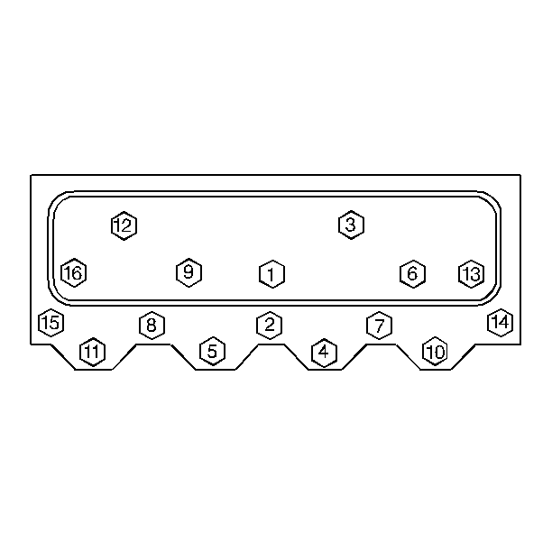
Removal Procedure
- Disconnect the negative battery cable. Refer to
Caution: Unless directed otherwise, the ignition and start switch must be in the OFF or LOCK position, and all electrical loads must be OFF before servicing any electrical component. Disconnect the negative battery cable to prevent an electrical spark should a tool or equipment come in contact with an exposed electrical terminal. Failure to follow these precautions may result in personal injury and/or damage to the vehicle or its components.
in General Information. - Remove the engine cover. Refer to Interior Trim.
- Remove the intake manifold. Refer to Intake Manifold Replacement .
- Remove the air conditioning compressor and the air conditioning compressor bracket and lay aside (left cylinder head). Refer to Compressor Replacement in Heating, Ventilation and Air Conditioning.
- Remove the generator and the generator brackets (right cylinder head). Refer to Generator Replacement in Engine Electrical.
- Remove the exhaust manifold. Refer to Exhaust Manifold Replacement .
- Remove the spark plugs. Refer to Spark Plugs Replacement in Engine Electrical.
- Disconnect the temperature sensor electrical connector at the cylinder head.
- Remove the pushrods. Refer to Valve Rocker Arm and Push Rod Replacement .
- Remove the cylinder head bolts.
- Remove the cylinder head.
- Remove the head gasket.
- Clean the carbon deposits from the combustion chambers.
- Clean all traces of the old head gasket from the cylinder head and the block.
- Clean the cylinder head bolt threads and the threads in the block.
- Inspect the sealing surfaces of the block and the cylinder head damage.
Installation Procedure
- Install the head gasket.
- Install the cylinder head.
- Install the cylinder head bolts.
- Coat the threads of the cylinder head bolts with sealing compound GM P/N 12346004 or the equivalent.
- Install the cylinder head bolts finger tight.
- Tighten the first sequence to 40 N·m (30 lb ft).
- Tighten the second sequence to 80 N·m (60 lb ft).
- Tighten the final sequence to 115 N·m (80 lb ft).
- Install the pushrods. Refer to Valve Rocker Arm and Push Rod Replacement .
- Connect the temperature sensor electrical connector.
- Install the spark plugs. Refer to Spark Plugs Replacement in Engine Electrical.
- Install the exhaust manifold. Refer to Exhaust Manifold Replacement .
- Install the generator and the generator brackets (right cylinder head). Refer to Generator Replacement in Engine Electrical.
- Install the air conditioning compressor and the bracket (left cylinder head). Refer to Refer to Compressor Replacement in Heating, Ventilation and Air Conditioning.
- Install the intake manifold. Refer to Intake Manifold Replacement .
- Install the engine cover.
- Change the oil and the filter.
Important:
• Transfer all necessary parts. • Do not use sealer on the composition gaskets. • Do not place the gasket over the block dowel pins with the bead
up.
Carefully guide the cylinder head into place over the dowel pins and the gasket.

Tighten
Notice: Use the correct fastener in the correct location. Replacement fasteners must be the correct part number for that application. Fasteners requiring replacement or fasteners requiring the use of thread locking compound or sealant are identified in the service procedure. Do not use paints, lubricants, or corrosion inhibitors on fasteners or fastener joint surfaces unless specified. These coatings affect fastener torque and joint clamping force and may damage the fastener. Use the correct tightening sequence and specifications when installing fasteners in order to avoid damage to parts and systems.
