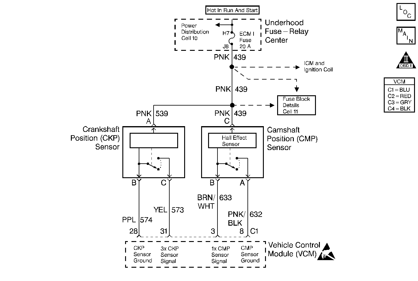
Circuit Description
The Crankshaft Position (CKP) sensor sends a reference signal to the Vehicle Control Module (VCM) in order to indicate the crankshaft position and the RPM so that the VCM can determine when to pulse the ignition coil, the fuel injectors, and the control ignition timing. This is a type D DTC.
Conditions for Setting the DTC
The following conditions will set the DTC:
| • | The Crankshaft Position sensor signal is missing for at least 0.5 seconds. |
| • | The engine cranking and the VCM receives 4 or more CAM Shaft Position signals without a Crankshaft Position sensor signal. |
Action Taken When the DTC Sets
The VCM stores the DTC in History if the VCM detects an intermittent problem.
Conditions for Clearing the MIL/DTC
A history DTC will clear if no fault conditions have been detected for 40 warm-up cycles (the coolant temperature has risen 40°F from the start-up coolant temperature and the engine coolant temperature exceeds 160°F during that same ignition cycle) or the scan tool clearing feature has been used.
Diagnostic Aids
A poor connection, a rubbed through wire insulation, or a wire that is broken inside the insulation may cause an intermittent problem.
Thoroughly check any circuitry, that is suspected of causing the intermittent complaint for the following conditions:
| • | Backed out terminals |
| • | Improper mating |
| • | Broken locks |
| • | Improperly formed or damaged terminals |
| • | Poor terminal to wiring connections |
| • | Physical damage to the wiring harness |
Inspect the face of the CKP sensor for metal shavings. This could result in an intermittent DTC P0339
Refer to Intermittent Conditions .
Test Description
The numbers below refer to the step numbers on the diagnostic table.
-
This step determines if the DTC P0336 is the result of a hard failure or an intermittent condition.
-
This step determines if the VCM is receiving the Crankshaft Position sensor pulses.
-
This step checks the ignition feed circuit to the Crankshaft Position sensor.
-
This step checks the Crankshaft Position sensor low circuit.
-
This step checks the Crankshaft Position Sensor.
Step | Action | Value(s) | Yes | No |
|---|---|---|---|---|
1 |
Important: Before clearing DTCs, use the scan tool in order to record freeze frame and the failure records for reference because the Clear Info function will lose the data. Was the Powertrain On-Board Diagnostic (OBD) System Check performed? | -- | ||
Does the vehicle start and continue to run? | -- | Go to Diagnostic Aids | ||
Is the test lamp ON? | -- | |||
Connect the test lamp between the CKP sensor ignition feed and the CKP sensor Low circuit. Is the test lamp ON? | -- | |||
Is the duty cycle within the specified value? | V-6 - 40%-60% | |||
Repair the open or short to ground in the CKP sensor ignition feed circuit. Refer to Wiring Repairs in Engine Electrical. Is the action complete? | -- | -- | ||
7 | Check the CKP sensor Low circuit for an open. Was the problem found? | -- | ||
8 | Check for an open in the CKP sensor (3X) signal circuit or an open in the CKP sensor Low circuit. Was a problem, found? | -- | ||
9 | Replace the CKP sensor. Refer to Crankshaft Position (CKP) Sensor Replacement . Important: Inspect the CKP sensor mounting surface to insure the surface is clean and free of debris. Is the action complete? | -- | -- | |
10 | Repair as necessary. Is the action complete? | -- | -- | |
11 | Replace the VCM. Important: If the VCM is faulty, reprogram the VCM. Refer to VCM Replacement/Programming (With KS Calibration PROM) . Is the action complete? | -- | -- | |
12 |
Does the scan tool indicate that this diagnostic ran and passed? | -- | ||
13 | Using the scan tool, select Capture Info and Review Info. Are any DTCs displayed that have not been diagnosed? | -- | Go to The Applicable DTC Table | System OK |
