Removal Procedure
- Disconnect the battery negative cable from the battery. Refer to Battery Cable Replacement in Engine Electrical.
- Remove the engine cover. Refer to Engine Cover in Interior Trim.
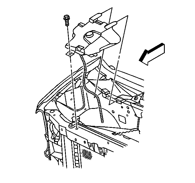
- Remove the coolant recovery reservoir. Refer to Coolant Recovery Reservoir Replacement
- Remove the air cleaner assembly. Refer to Air Cleaner Assembly Replacement
- Remove the air cleaner intake duct. Refer to Air Cleaner Outlet Duct Replacement
- Remove the front bumper. Refer to Front Bumper Impact Bar Replacement in Frame and Bumpers.
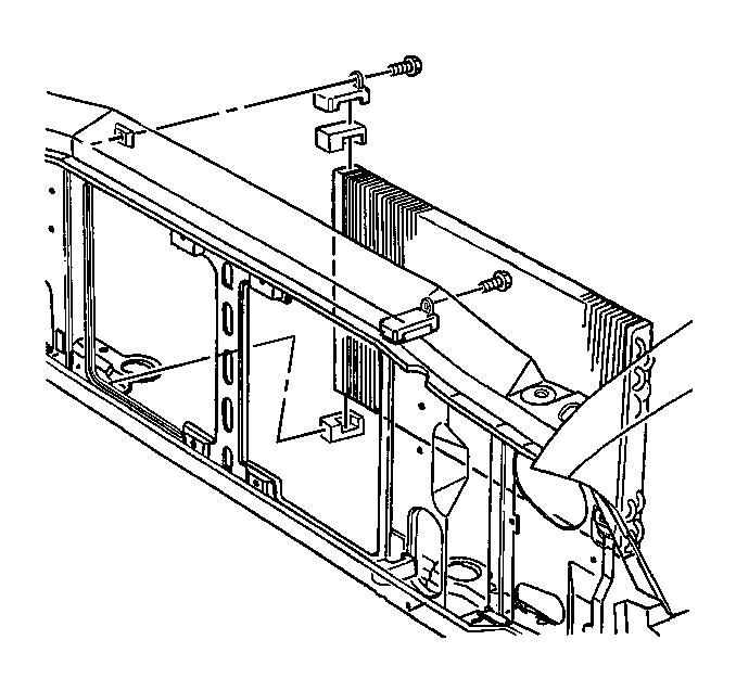
- Remove the radiator grille assembly. Refer to Radiator Grille in Sheet Metal.
- Remove the radiator support. Refer to Radiator Support in Sheet Metal.
- Remove the A/C condenser. Refer to Condenser in HVAC.
- Remove the radiator. Refer to Radiator Replacement
- Remove the ground straps. Refer to Engine Ground Strap Replacement
- Remove the fan clutch from the water pump. Refer to Fan Clutch Replacement
- Remove the heater hoses from the engine .Refer to Heater Hoses in Heater and Ventilation.
- Remove the engine wiring harness.
- Remove the accelerator control cable and the cruise control cable, if equipped. Refer to Accelerator Control Cable Replacement
- Remove the generator from the mounting bracket. Refer to Generator Replacement
- Remove the generator mounting bracket using the following procedure:
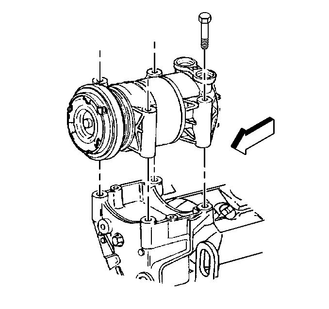
- Remove the A/C compressor from the mounting bracket. Refer to Compressor in HVAC.
- Remove the power steering pump from the mounting bracket. Refer to Power Steering Pump in Power Steering Gear and Pump.
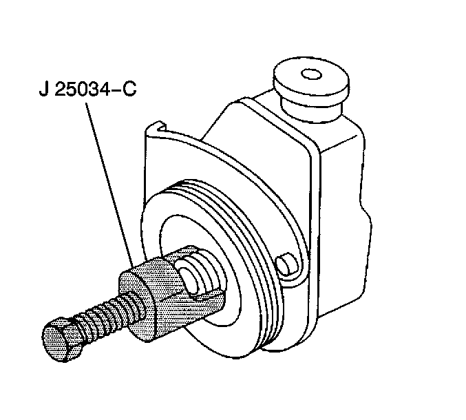
- Remove the pulley from the power steering pump. Refer to Power Steering Pump in Power Steering Gear and Pump.
- Remove the power steering pump mounting bracket using the following procedure:
- In order to allow access for the lifting device, remove the upper intake manifold. Refer to Intake Manifold Replacement
- Remove the fuel pipes from the rear of the engine. Refer to Fuel Hose/Pipes Replacement - Engine Compartment in Engine Controls-5.0/5.7L.
- Remove the transmission oil level indicator and tube. Refer to Filler Tube Replacement
- Remove the transmission shift cable connector. Refer to Shift Cable Replacement
- Raise the vehicle and support with safety stands. Refer to Lifting and Jacking the Vehicle
- Drain the engine oil. Refer to Engine Oil and Oil Filter Replacement
- Remove the exhaust pipes from the exhaust manifolds. Refer to Catalytic Converter Replacement
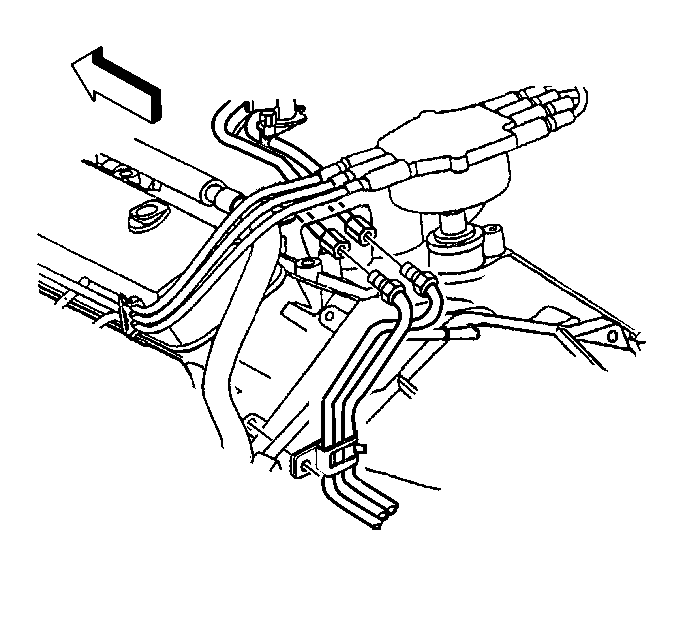
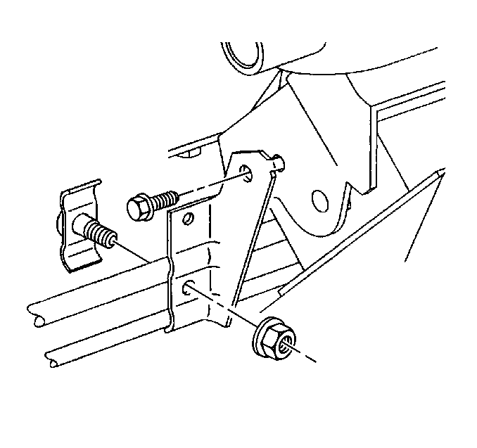
- Remove the engine oil cooler lines from the retaining brackets.
- Remove the engine oil cooler lines from the engine. Refer to Engine Oil Cooler Hose/Pipe Replacement
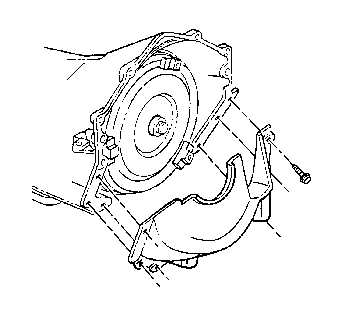
- Remove the flywheel cover.
- Remove the torque converter bolts from the flywheel. Refer to Engine Flywheel Replacement
- Remove the starter motor. Refer to Starter Motor Replacement
- Remove the transmission cooler lines from the engine. Refer to Oil Cooler Hose/Pipe Replacement
- Remove the bolts holding the transmission to the engine. Refer to Transmission Replacement and Transmission Replacement .
- Remove the safety stands and lower the vehicle. Refer to Lifting and Jacking the Vehicle
- Install a length of chain, using GM P/N 23503910 attaching bolt to the rear of the left cylinder head.
- Support the transmission with a strap between the frame rails.
- Attach a suitable lifting device to the chain.
- Remove the engine mount through bolts. Refer to Engine Mount Replacement
- Remove the engine mounts from the frame. Refer to Engine Mount Replacement
- Remove the engine assembly from the vehicle.
Caution: Before servicing any electrical component, the ignition and start switch must be in the OFF or LOCK position and all electrical loads must be OFF, unless instructed otherwise in these procedures. If a tool or equipment could easily come in contact with a live exposed electrical terminal, also disconnect the negative battery cable. Failure to follow these precautions may cause personal injury and/or damage to the vehicle or its components.
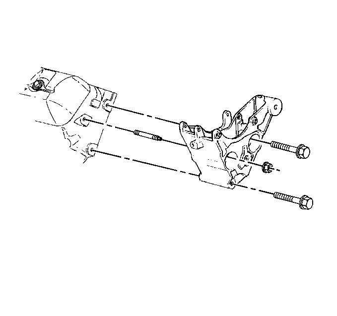
| • | Remove three bolts from the front of the bracket. |
| • | Remove one nut from the front of the bracket. |
| • | Slide the bracket off of the stud. |
| • | Remove the stud from the cylinder head. |
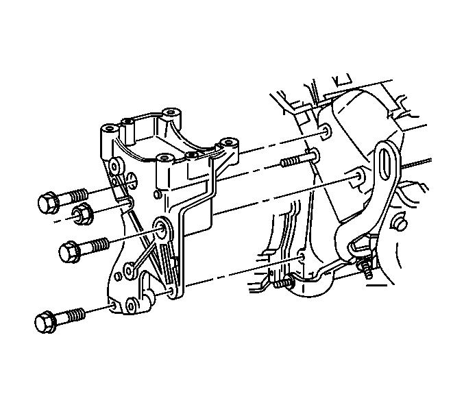
| • | Remove three bolts from the front of the bracket. |
| • | Remove one nut from the front of the bracket. |
| • | Slide the bracket off of the stud. |
| • | Remove the stud from the cylinder head. |
Installation Procedure
- Install the engine assembly to the vehicle.
- Install the engine mounts to the frame. Refer to Engine Mount Replacement
- Install the engine mount through bolts. Refer to Engine Mount Replacement
- Remove the lifting device from the chain.
- Support the transmission with a strap between the frame rails.
- Raise the vehicle and support with safety stands. Refer to Lifting and Jacking the Vehicle
- Install the bolts from the transmission to the engine. Refer to Transmission Replacement
- Install the transmission cooler lines to the engine block. Refer to Oil Cooler Hose/Pipe Replacement
- Install the torque converter bolts to the flywheel. Refer to Engine Flywheel Replacement
- Install the flywheel cover.
- Install the starter motor. Refer to Starter Motor Replacement
- Install the engine oil cooler lines to the engine. Refer to Engine Oil Cooler Hose/Pipe Replacement
- Install the engine oil cooler lines to the retaining brackets.
- Install the exhaust pipes to the exhaust manifolds. Refer to Catalytic Converter Replacement
- Install the exhaust pipes to the exhaust manifolds. Refer to Catalytic Converter Replacement
- Remove the safety stands and lower the vehicle. Refer to Lifting and Jacking the Vehicle
- Install the transmission shift cable connector. Refer to Shift Cable Replacement
- Install the transmission oil level indicator and the tube Refer to Filler Tube Replacement
- Install the fuel pipes to the rear of the engine. Refer to Fuel Hose/Pipes Replacement - Engine Compartment in Engine Controls-5.0/5.7L.
- Install the upper intake manifold to the engine. Refer to Intake Manifold Replacement
- Install the power steering pump mounting bracket using the following procedure:
- Install the power steering pump to the mounting bracket. Refer to Power Steering Pump in Power Steering Pump and Gear.
- Install the A/C compressor to the mounting bracket. Refer to Compressor in HVAC.
- Install the generator mounting bracket using the following procedure:
- Install the generator to the mounting bracket. Refer to Generator Replacement
- Install the accelerator control cable and the cruise control cable, if equipped. Refer to Accelerator Control Cable Replacement
- Install the engine wiring harness.
- Install the heater hoses to the engine block. Refer to Heater Hoses in Heater and Ventilation.
- Install the fan clutch to the water pump. Refer to Fan Clutch Replacement
- Install the ground straps. Refer to Engine Ground Strap Replacement
- Install the radiator. Refer to Radiator Replacement
- Install the A/C condenser. Refer to Condenser in HVAC.
- Install the radiator support. Refer to Radiator Support in Sheet Metal.
- Install the radiator grille assembly. Refer to Radiator Grille in Sheet Metal.
- Install the front bumper. Refer to Front Bumper Impact Bar in Frame and Bumpers.
- Install the air cleaner intake duct. Refer to Air Cleaner Outlet Duct Replacement
- Install the air cleaner assembly. Refer to Air Cleaner Assembly Replacement
- Install the coolant recovery reservoir. Refer to Coolant Recovery Reservoir Replacement
- Install the engine cover. Refer to Engine Cover in Interior Trim.
- Connect the battery negative cable to the battery. Refer to Battery Cable Replacement in Engine Electrical.
- Fill the engine with the proper quantity and grade of engine oil. Refer to Engine Oil and Oil Filter Replacement
- Fill the cooling system with the proper quantity and type of coolant. Refer to Cooling System Draining and Filling


Notice: Use the correct fastener in the correct location. Replacement fasteners must be the correct part number for that application. Fasteners requiring replacement or fasteners requiring the use of thread locking compound or sealant are identified in the service procedure. Do not use paints, lubricants, or corrosion inhibitors on fasteners or fastener joint surfaces unless specified. These coatings affect fastener torque and joint clamping force and may damage the fastener. Use the correct tightening sequence and specifications when installing fasteners in order to avoid damage to parts and systems.
| • | Install the stud to the cylinder head. |
Tighten
Tighten the stud to 22 N·m(16 lb ft).
| • | Loosely assemble the bracket over the stud. |
| • | Install a nut to the stud finger tight. |
| • | Install three bolts finger tight. |
| • | Install two nuts to the power steering pump finger tight. |
Tighten
Tighten the nuts and bolts to 44 N·m(32 lb ft).


| • | Install the stud to the cylinder head. |
Tighten
Tighten the stud to 22 N·m(16 lb ft).
| • | Loosely assemble the bracket over the stud. |
| • | Install a nut the stud finger tight. |
| • | Install three bolts finger tight. |
Tighten
Tighten the nuts and bolts to 44 N·m(32 lb ft).

