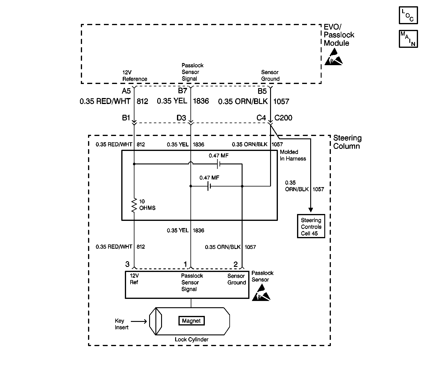
Circuit Description
The EVO/Passlock module will read an analog voltage from the Passlock sensor. Based on an internal reference the EVO/Passlock module will determine if the measured voltage is open, shorted to ground, a valid code, or a tamper code. There are 10 possible valid code combinations. The EVO/Passlock module will only accept the last learned valid code.
Diagnostic Aids
| • | Prior to cranking, if a problem developed to prevent the Passlock sensor signal from reporting to the EVO/Passlock module, the vehicle will not start and DTC B2958 will not be set. In this case, the scan tool will still read "Passlock Code Open" after cranking. |
| • | When replacing the Passlock sensor, all the sensor components; the lock, the sensor, the filter, and the harness, are included as a replacement part and must be replaced. |
| • | Use the scan tool in order to test the Passlock data voltage and the Passlock code. |
| • | Perform a visual inspection of the wiring and the connectors. |
| • | Inspect the Passlock sensor harness for an intermittent or poor connections (including the in-line connector). Refer to Intermittents and Poor Connections . |
Test Description
The numbers below refer to the numbers on the diagnostic table.
-
This step determines if the Passlock data terminal has an open condition or a short to battery.
-
This step determines if the Passlock sensor power is available at the EVO/Passlock module. If CKT 812 is shorted to ground, DTC B2947 will set. Diagnosing and repairing DTC B2947 may eliminate the engine cranking but not starting condition.
-
This step tests the Passlock sensor ground.
-
This step tests for an open in any of the Passlock sensor lines.
-
This step tests for a short to battery on the Passlock sensor signal line.
-
This step isolates the problem between the Passlock sensor and CKT 1836.
Step | Action | Value(s) | Yes | No | ||||||||||||
|---|---|---|---|---|---|---|---|---|---|---|---|---|---|---|---|---|
1 | Did you perform the VTD Diagnostic System Check? | -- | Go to Step 2 | |||||||||||||
Is the voltage within the specified range? | 4.9-5.0 volts. | Go to Step 3 | Go to Step 7 | |||||||||||||
Use a J 39200 DMM in order to measure the voltage from the EVO/Passlock module connector terminal A5 to ground. Is the voltage within the specified range? | 9-16 volts. | Go to Step 4 | ||||||||||||||
Use a J 39200 DMM in order to measure the voltage between the EVO/Passlock module connector terminal A5 and terminal B5. Is the voltage within the specified range? | 9-16 volts. | Go to Step 5 | Go to Step 8 | |||||||||||||
Is the resistance within the specified range on all 3 circuits? | 0-5ohms | Go to Step 6 | Go to Step 11 | |||||||||||||
6 |
If all the above are OK, Replace the Passlock sensor in the electronic column lock module assembly.
Is the repair complete? | -- | Go to Step 12 | -- | ||||||||||||
Is the voltage above the specified value? | 1.0 volt | Go to Step 9 | Go to Step 8 | |||||||||||||
8 |
Is the repair complete? | -- | Go to Step 12 | -- | ||||||||||||
Is the voltage above the specified value? | 1.0 volt | Go to Step 10 | Go to Step 06 | |||||||||||||
10 | Repair the short to battery in CKT 1836. Is the repair complete? | -- | -- | |||||||||||||
11 | Repair the open in the appropriate circuit from the following list:
Is the repair complete? | -- | -- | |||||||||||||
12 |
Is the repair complete? | -- | -- |
