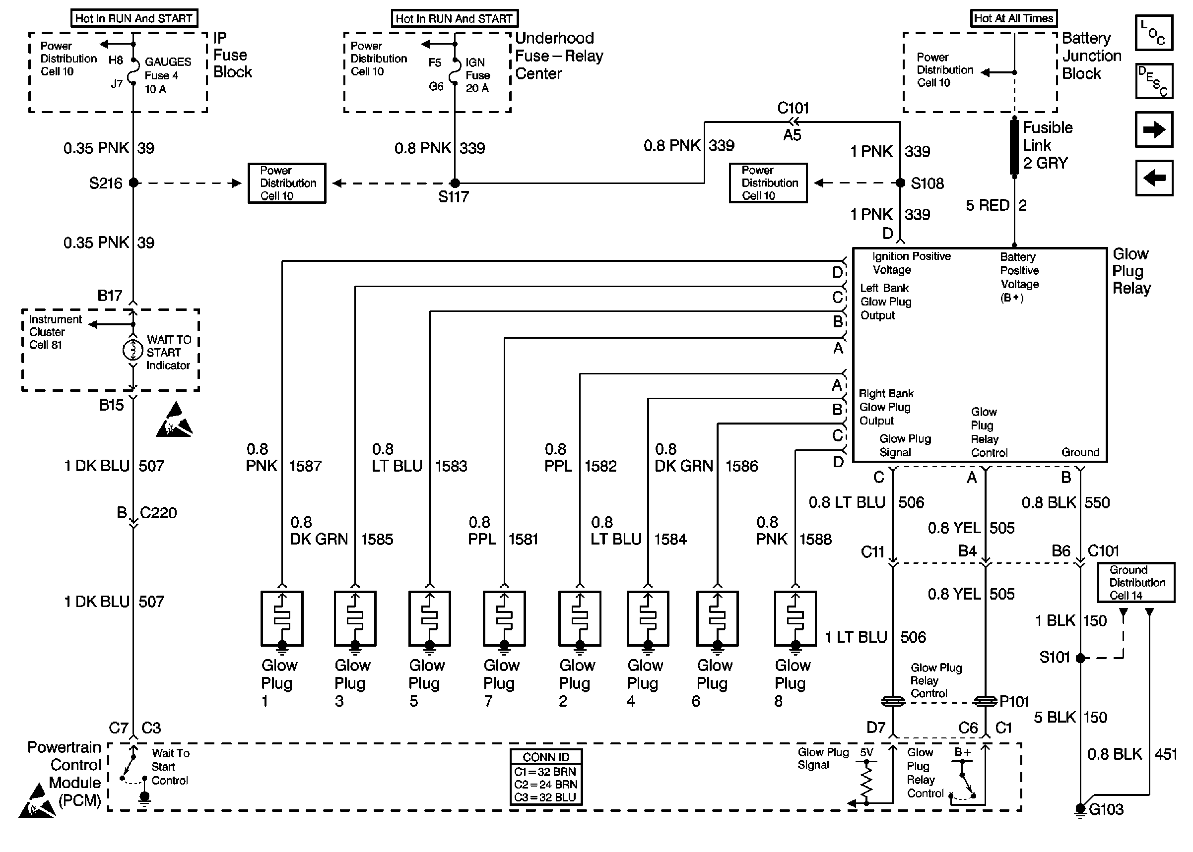
Refer to Engine Control Schematics
Cell 22: Glow Plug Controls California Emissions

.
Circuit Description
Important: This check only applies to the Federal Glow Plug System (the Federal Glow Plug System does not have the ability to detect for a glow plug failure). The California Glow Plug System can determine glow plug failure by setting a DTC P0380.
The glow plug system helps provide the heat required to begin combustion when starting the engine at cold ambient temperatures. The glow plugs are heated before and during cranking, as well as during the initial engine operation. The PCM controls the amount of time the glow plugs are energized by monitoring coolant temperatures and the glow plug voltage. This system check will check the glow plugs and the glow plug feed circuit coming from the relay.
Diagnostic Aids
If the glow plug relay is stuck in the ON position, check for proper operation of glow plugs. When the glow plugs are commanded ON by the scan tool, an internal PCM timer protects the glow plugs from damage by cycling them ON for 3 seconds and then OFF for 12 seconds. Most glow plug system failures are covered by DTC P0380. If no DTCs are stored ,note if the vehicle is hard to start and white smoke is present during cranking, or after the vehicle is started. The most likely cause of failure is the glow plugs.
Test Description
The number(s) below refer to the number(s) on the diagnostic table.
-
This step will ensure that the OBD system check is performed.
-
This step will ensure that there are no other DTCs stored that will affect the operation of the glow plug system.
-
This step will check each glow plug for an open.
-
This step will check each glow plug feed circuit for an open.
Step | Action | Value(s) | Yes | No | ||||||
|---|---|---|---|---|---|---|---|---|---|---|
|
Important: Before clearing the DTCs, use the Scan Tool Capture Info in order to record the Freeze Frame and the failure records for reference, as the data will be lost when the Clear Info function is used. Was the Powertrain On-Board Diagnostic (OBD) System Check performed? | -- | |||||||||
Is DTC:
stored as history or current codes? | -- | Go to the Applicable DTC Table | ||||||||
Do all of the glow plugs turn the test light ON? | -- | |||||||||
Does each circuit turn the test light ON? | -- | |||||||||
5 | Does the test light stay ON all the time for each glow plug terminal (even when the glow plugs aren't commanded ON)? | -- | ||||||||
6 |
Is the test light ON for all terminals? | -- | ||||||||
7 | Repair the short to voltage on the glow plug output circuit or the short to voltage on the glow plug signal circuit. Is the action complete? | -- | -- | |||||||
8 | Replace the glow plug relay. Refer to Glow Plug Relay Replacement . Is the action complete? | -- | -- | |||||||
9 | Replace all of the glow plugs that do not turn the test light ON. Refer to Glow Plug Relay Replacement . Is the action complete? | -- | -- | |||||||
10 | Repair the open in each circuit that does not turn the test light ON. Is the action complete? | -- | -- | |||||||
11 | Operate the vehicle within the conditions under which system was noted. Does the system operate properly? | -- | The System is OK |
