Removal Procedure
Tools Required
| • | Refer to J 41711 Injection Pump Wrench |
| • | Refer to J 29872-A Injection Pump adjusting tool. |
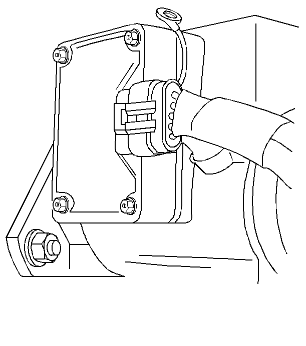
- Remove the intake manifold in order to gain access to the fuel solenoid driver. Refer to Intake Manifold Replacement in Engine Mechanical. The fuel solenoid driver is located on the left side of the injection pump.
- Scribe a reference mark on the engine front cover and the injection pump housing to assist in correctly locating the injection pump during reassembly.
- Loosen the injection pump retaining nuts approximately ½ turn, using an J 41711 injection pump wrench. Do not remove the nuts.
- Rotate the pump to the passegner side of the vehicle until it stops, using an J 29872-A injection pump adjusting tool.
- Retighten the top injection pump retaining nut using J 41711 injection pump wrench.
- Disconnect the fuel solenoid driver wiring connector at the injection pump.
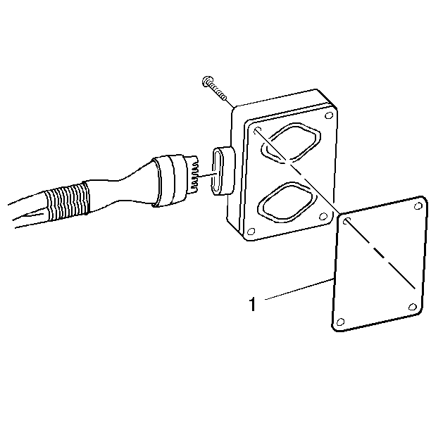
- Loosen the four fuel solenoid driver mounting screws until the screws are free from the injection pump.
- Discard the heat transfer pad (1) and the mounting screws.
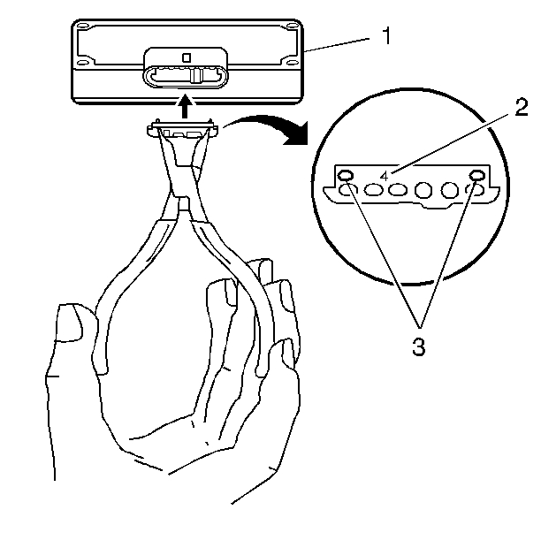
- Remove the fuel solenoid calibrating resistor using a snap ring pliers. The calibrating resistor is located on a small circuit board which is located in the PMD connector housing and is placed over the PMD terminal pins. This calibrating resistor circuit board has two outboard holes (3) which can be grabbed with snap ring pliers.


Installation Procedure
- Install the calibrating resistor in the new fuel solenoid driver using snap ring pliers (the resistor is keyed to fit in only one way). Install the resitor with an indication number facing upward. If the fuel solenoid driver calibrating resistor is missing. DTC 1218 will set.
- Place the new heat transfer pad (1) on the side of the new fuel solenoid driver and insert the four fuel solenoid driver mounting screws into the fuel solenoid driver.
- Align the fuel solenoid driver mounting screws with the holes in the pump housing and tighten.
- Connect the fuel solenoid driver wiring harness connector.
- Loosen the upper injection pump retaining nut approximately ½ turn using the J 41711 injection pump wrench. Do not remove the nut.
- Using the J 29872-A injection pump adjusting tool, rotate the pump back to it's original position using the reference mark you created in step 2 Removal Procedure.
- Install the intake manifold. Refer to Intake Manifold Replacement in Engine Mechanical.
- Peform the injection timing adjustment procedure. Refer to Fuel Injection Pump Timing Adjustment .

Important: The calibrating resistor is specific to the injection pump. Do not damage the resistor. The calibrating resistor indication number (2) is located on the front of the calibrating resistor. If the calbirating resistor is damaged or lost, the injection pump must be removed for replacement or taken to a Stanadyne dealer for calibration.

Important: The pad is designed to transfer heat geerated by the PMD to the pump housing so it can be dissipated. Do not install the fuel solenoid driver without a new heat transfer pad. Do not reuse a heat tranfer pad. Use a new heat transfer pad only. The heat transfer pad is required to prevent rapid failure of the fuel solenoid driver from overheating. It is not a seal or a gasket. The pump comes with new screws and a new heat transfer pad.
Notice: Use the correct fastener in the correct location. Replacement fasteners must be the correct part number for that application. Fasteners requiring replacement or fasteners requiring the use of thread locking compound or sealant are identified in the service procedure. Do not use paints, lubricants, or corrosion inhibitors on fasteners or fastener joint surfaces unless specified. These coatings affect fastener torque and joint clamping force and may damage the fastener. Use the correct tightening sequence and specifications when installing fasteners in order to avoid damage to parts and systems.
Important: Do not over tighten the fuel solenoid driver mounting screws. Damage to the fuel solenoid driver will result. Damage to the PMD from overtightening the mounting screws is very common.
Tighten
Tighten the fuel solenoid driver mounting screws to 2.75 N·m
(23 lb in.)

