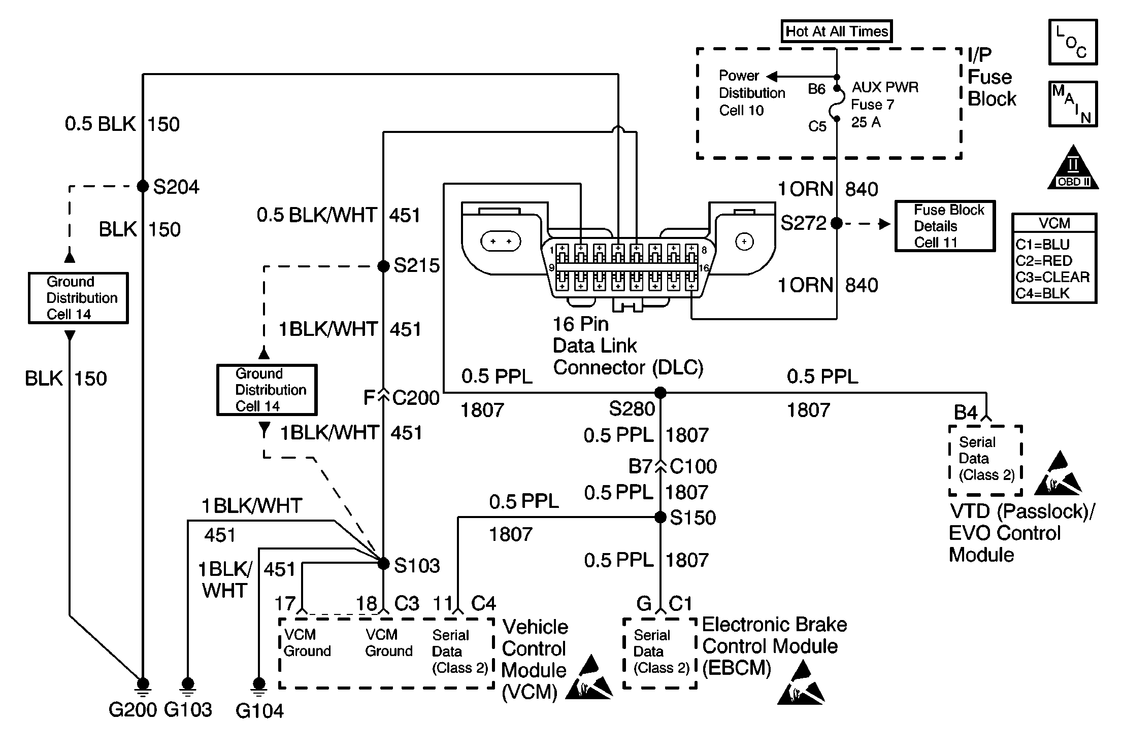
Circuit Description
This diagnostic will detect a loss of serial communication from the electronic brake control module (EBCM) to the control module. This serial communication is essential in order to distinguish misfire from a rough road condition.
Conditions for Running the DTC
| • | The vehicle speed is 2 km/h (1 mph). |
| • | The engine speed is less than 5800 RPM. |
| • | The engine load is less than 89 percent. |
| • | Engine misfire is detected. |
Conditions for Setting the DTC
A serial data malfunction is preventing the VCM from receiving rough road detection data.
Action Taken When the DTC Sets
| • | The control module stores the DTC in history after the first failure but will not illuminate the malfunction indicator lamp (MIL). |
| • | The control module records the operating conditions at the time the diagnostic fails. The control module stores the failure information in the scan tools Freeze Frame/Failure Records. |
Conditions for Clearing the MIL/DTC
| • | A history DTC will clear if no fault conditions have been detected for 40 warm-up cycles. |
| • | A warm-up cycle occurs when the coolant temperature has risen 22°C (40°F) from the startup coolant temperature and the engine coolant temperature exceeds 70°C (160°F) during the same ignition cycle. |
| • | Use the scan tool Clear Information function. |
Diagnostic Aids
Check for the following conditions:
An intermittent may be caused by any of the following conditions:
| • | A poor connection |
| • | Rubbed through wire insulation |
| • | A broken wire inside the insulation |
Thoroughly inspect any circuitry that is suspected of causing the intermittent complaint. Refer to Testing for Intermittent Conditions and Poor Connections in Wiring Systems.
If a repair is necessary, refer to Wiring Repairs or Connector Repairs in Wiring Systems.
Test Description
The numbers below refer to the step numbers on the diagnostic table.
Step | Action | Values | Yes | No |
|---|---|---|---|---|
1 | Did you perform the Powertrain On-Board Diagnostic (OBD) System Check? | -- | Go to Step 2 | |
2 | Check for any U-Codes. Did you find any U-Codes? | -- | Go to the applicable DTC table | Go to Step 3 |
Did you find a problem? | -- | Go to Step 4 | Go to Diagnostic System Check in Antilock Brake System | |
4 | Repair the circuit as necessary. Refer to Wiring Repairs or Connector Repairs in Wiring Systems. Is the action complete? | -- | Go to Step 5 | -- |
5 |
Does the scan tool indicate the diagnostic Passed? | -- | Go to Step 6 | Go to Step 2 |
6 | Does the scan tool display any additional undiagnosed DTCs? | -- | Go to the applicable DTC table | System OK |
