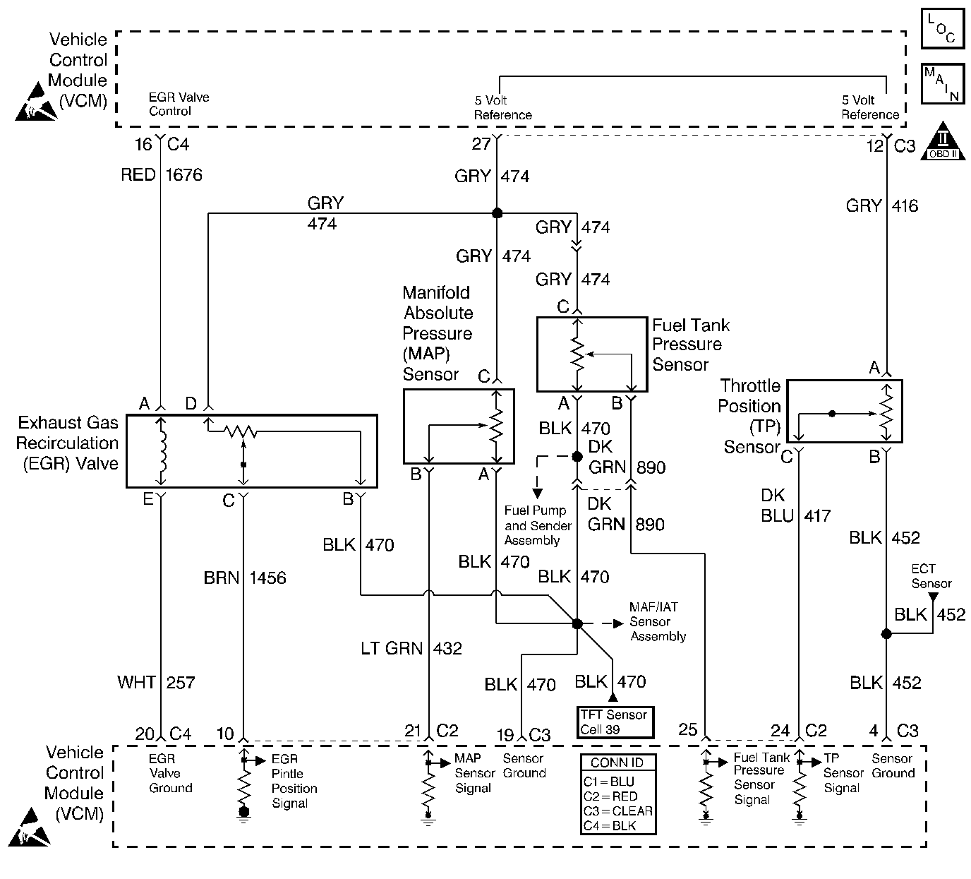
Circuit Description
The fuel tank pressure sensor responds to changes in the fuel tank pressure or vacuum. This information is used in order to detect vacuum decay or an excessive vacuum during the evaporative emission (EVAP) diagnostic routing. The fuel tank pressure sensor signal voltage to the vehicle control module (VCM) varies from a minimum of about 0.1 volts with pressure in the fuel tank to above 4.0 volts with a high vacuum in the fuel tank.
The fuel tank pressure sensor display on the scan tool has an auto zero feature which occurs at each ignition cycle and is corrected according to the barometric pressure. Because of this, the fuel tank pressure sensor display may not accurately reflect the actual output of the sensor or the conditions within the fuel tank.
The fuel tank pressure sensor diagnosis table is intended to isolate and diagnose the electrical problems with the sensor wiring or the sensor.
Conditions for Running the DTC
The ignition switch is in the RUN position.
Conditions for Setting the DTC
The fuel tank pressure sensor voltage is less than 0.1 volt for more than 5 seconds.
Action Taken When the DTC Sets
The VCM turns ON the malfunction indicator lamp (MIL) after 2 consecutive driving cycles with the fault active.
Conditions for Clearing the MIL or DTC
| • | The control module turns OFF the MIL after 3 consecutive drive trips when the test has run and passed. |
| • | A history DTC will clear if no fault conditions have been detected for 40 warm-up cycles. A warm-up cycle occurs when the coolant temperature has risen 22°C (40°F) from the startup coolant temperature and the engine coolant reaches a temperature that is more than 70°C (158°F) during the same ignition cycle. |
| • | Use a scan tool in order to clear the DTCs. |
Diagnostic Aids
- Inspect the control module harness connectors for the following conditions:
- Inspect the wiring harness for damage. If the harness appears to be OK, observe the fuel tank pressure sensor display on the scan tool while moving the connectors and the wiring harnesses related to the sensor. A change in the display will indicate the location of the fault. Refer to Wiring Repairs in Wiring Systems if a fault in the wiring is found.
| • | Improper mating |
| • | Broken locks |
| • | Improperly formed |
| • | Damaged terminals |
Test Description
The numbers below refer to the step numbers on the diagnostic table.
Step | Action | Value(s) | Yes | No | ||||||||
|---|---|---|---|---|---|---|---|---|---|---|---|---|
1 | Did you perform the Powertrain On-Board Diagnostic (OBD) System Check? | -- | ||||||||||
2 |
Does the scan tool display indicate the fuel tank pressure sensor above the specified value? | 7.2 in. H2O | ||||||||||
3 | This DTC is intermittent. Are any additional DTCs stored? | -- | Go to the applicable DTC table | Go to Diagnostic Aids | ||||||||
4 |
Is the voltage near the specified value? | 5.0 V | ||||||||||
Does the EVAP fuel tank pressure sensor display pressure more than the specified value? | -16.50 in. H2O | |||||||||||
6 | Check for an open in the 5 volt reference circuit. Did you find a problem? | -- | ||||||||||
7 | Check for a short to ground in the 5 volt reference circuit. Did you find a problem? | -- | ||||||||||
8 | Check the 5 volt reference circuit for a poor terminal connection at the VCM. Did you find a problem? | -- | ||||||||||
9 | Check the fuel tank pressure sensor signal for an open or a short to ground. Did you find a problem? | -- | ||||||||||
10 | Check the fuel tank pressure sensor signal terminal connection at the VCM. Did you find a problem? | -- | ||||||||||
11 | Check the connector at the fuel tank pressure sensor for:
Did you find a problem? | -- | ||||||||||
12 | Replace the fuel tank pressure sensor. Refer to Fuel Tank Pressure Sensor Replacement . Is the action complete? | -- | -- | |||||||||
13 | Repair the circuit as necessary. Refer to Wiring Repairs in Wiring Systems. Is the action complete? | -- | -- | |||||||||
14 |
Important: The replacement VCM must be programmed. Replace the VCM. Refer to VCM Replacement/Programming . Is the action complete? | -- | -- | |||||||||
15 |
Does the scan tool indicate the diagnostic Passed? | -- | ||||||||||
16 | Does the scan tool display any additional undiagnosed DTCs? | -- | Go to the applicable DTC table | System OK |
