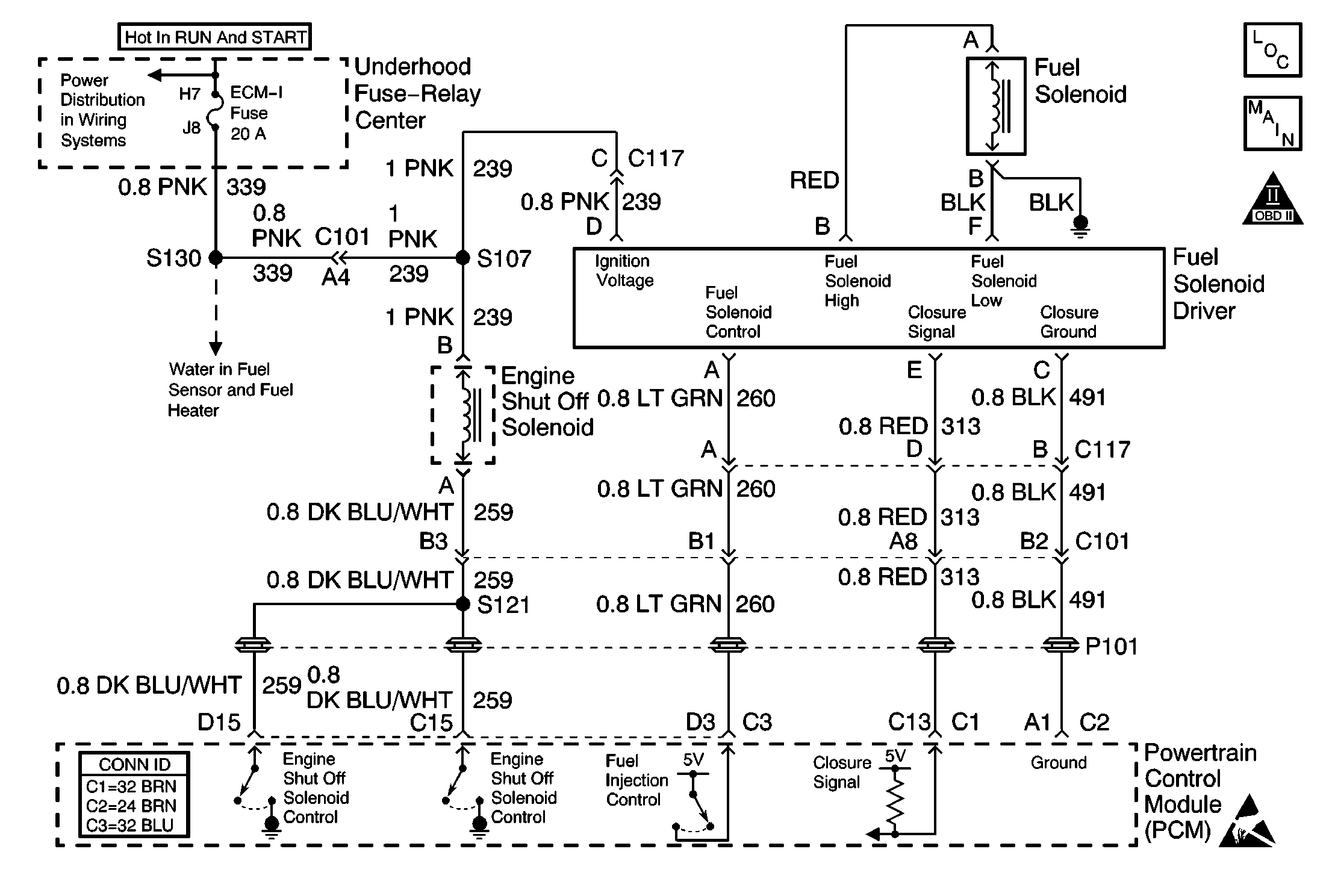
Circuit Description
The injection pump fuel supply line has a solenoid controlled shutoff which is located in the injection pump. When the solenoid is energized with the key in the RUN position, the valve is open and the fuel is supplied to the injection pump. By providing a ground path, the powertrain control module (PCM) energizes the solenoid.
Conditions for Running the DTC
The PCM requested the engine shut-off (ESO) solenoid ON--test 1.
or
The PCM requested the engine shut-off (ESO) solenoid OFF--test 2.
Conditions for Setting the DTC
| • | The control circuit voltage at the PCM is less than 8 volts--test 1. |
| • | The conditions are met for 2 seconds. |
or
| • | The control circuit voltage at the PCM is more than 8 volts--test 2. |
| • | The conditions are met for 2 seconds. |
Action Taken When the DTC Sets
| • | The PCM will not illuminate the malfunction indicator lamp (MIL). |
| • | The PCM records the operating conditions at the time the diagnostic fails. This information is stored in the Failure Records. |
Conditions for Clearing the MIL/DTC
| • | A History DTC clears after 40 consecutive warm-up cycles, if this or any other emission related diagnostic does not report any failures. |
| • | Use a scan tool in order to clear the DTCs. |
Diagnostic Aids
An open in the control circuit or the ignition feed circuit will cause a DTC P0215. A no start condition will also exist. The scan tool has the ability to turn the engine shutoff solenoid ON and OFF. This can be used as a quick operational check.
Test Description
The umbers below refer to the step numbers on the diagnostic table.
-
This step will check the ESO control circuit for an open.
-
After repairing the circuit for a short to voltage, check the solenoid for proper operation.
Step | Action | Value(s) | Yes | No | ||||
|---|---|---|---|---|---|---|---|---|
1 |
Important: Before clearing any DTCs, use the scan tool in order to save the Freeze Frame and the Failure records for reference. The control module's data is deleted once the Clear Info function is used. Was the Powertrain On-Board Diagnostic (OBD) System Check performed? | -- | ||||||
2 |
Is the test lamp ON? | -- | ||||||
Is the test lamp ON? | -- | |||||||
4 |
Does the test lamp turn ON and OFF with each command? | -- | ||||||
5 | Check the ESO harness for a faulty connection and replace the terminals if necessary. Refer to Wiring Repairs in Wiring Systems. Did you perform a repair? | -- | ||||||
6 |
Is the action complete? | -- | -- | |||||
7 |
Is the test lamp ON? | -- | ||||||
8 | Repair the short to ground on the ESO control circuit. Refer to Wiring Repairs in Wiring Systems. Is the action complete? | -- | -- | |||||
9 |
Is the action complete? | -- | ||||||
Is the action complete? | -- | |||||||
11 | Replace the Engine Shutoff Solenoid. Refer to Engine Shutdown Solenoid Replacement . Is the action complete? | -- | -- | |||||
12 |
Important: The new PCM must be programmed. Refer to Powertrain Control Module Replacement/Programming . Replace the PCM. Is the action complete? | -- | -- | |||||
13 |
Does the scan tool indicate the diagnostic Passed? | -- | ||||||
14 | Does the scan tool display any additional undiagnosed DTCs? | -- | Go to the applicable DTC table | System OK |
