Tools Required
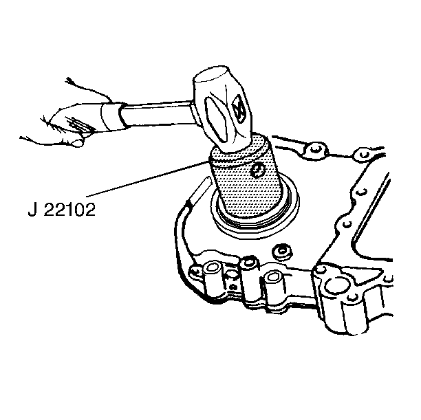
J 22102 Front Cover Seal Installer
Removal Procedure
Notice: Perform TDC Offset Recovery procedure if the timing chain, timing gears, engine front cover, crankshaft position sensor, crankshaft or other components affecting the timing are replaced.
- Disconnect the battery negative cables from the batteries. Refer to Battery Negative Cable Disconnection and Connection in Engine Electrical.
- Drain the cooling system. Refer to Cooling System Draining and Filling in Engine Cooling.
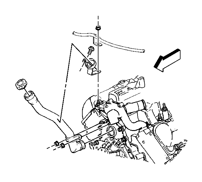
- Remove the engine oil fill tube from the front cover.
- Remove the crankshaft balancer from the crankshaft. Refer to Crankshaft Balancer Replacement .
- Remove the water pump from the engine front cover. Refer to Water Pump Replacement in Engine Cooling.
- Raise the vehicle and install safety stands (if needed). Refer to Lifting and Jacking the Vehicle in General Information.
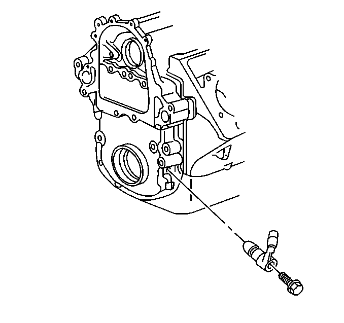
- Remove the crankshaft position sensor from the engine front cover.
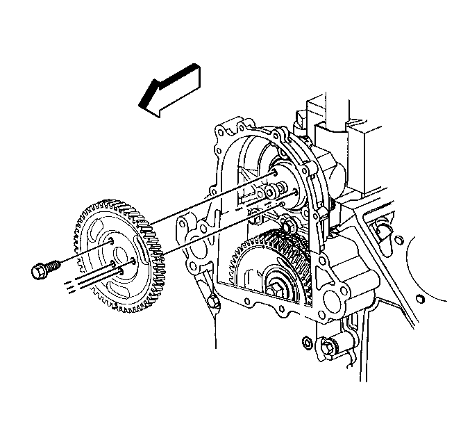
- Remove the fuel injection drive gear from the fuel injection pump.
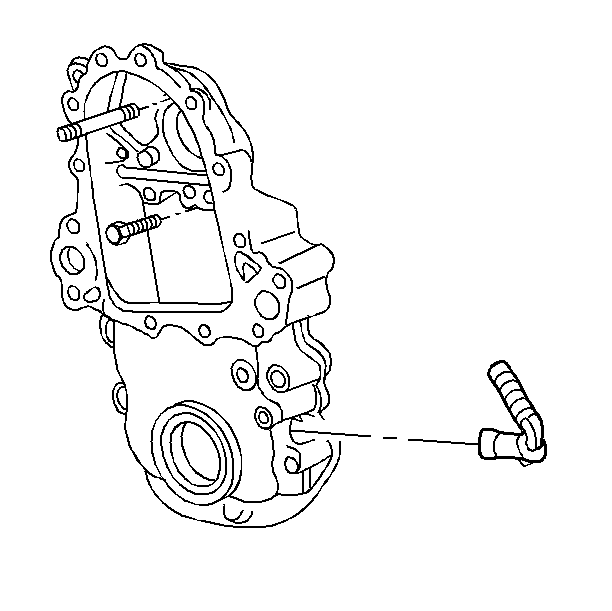
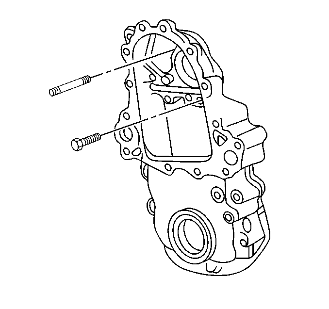
- Remove the bolts from the engine front cover.
- Remove the engine front cover from the engine block.
- Clean and inspect the sealing surface of the engine block.
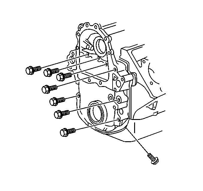
Important: Mark the fuel line clips, so that they can be re-installed on the proper stud.
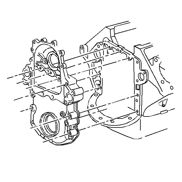
Installation Procedure
- Use the J 22102 to install the new front crankshaft front oil seal.
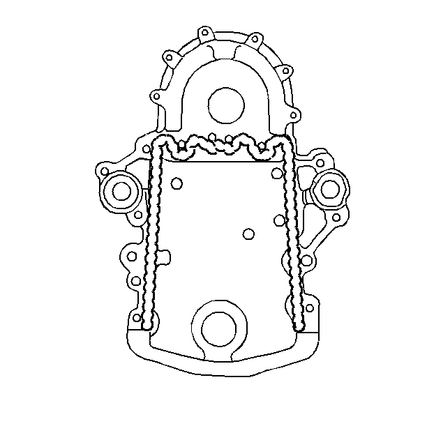
- Apply a 2 mm (3/32 in) bead of anaerobic sealant GM P/N 1052357 or equivalent to the engine front cover.
- Apply a 5 mm (3/16 in) bead of RTV sealant to the engine front cover sealing the surface that mates against the oil pan.
- Install the engine front cover to the engine block.
- Install the engine front cover bolts.
- Install the attaching bolts and the fuel injection pump studs.
- Install the fuel injection pump drive gear and bolts to the fuel injection pump.
- Install the crankshaft balancer to the crankshaft. Refer to Crankshaft Balancer Replacement .
- Install the crankshaft position sensor to the engine front cover.
- Remove the safety stands and lower the vehicle. Refer to Lifting and Jacking the Vehicle in General Information.
- Install the water pump to the engine block. Refer to Water Pump Replacement in Engine Cooling.
- Fill the cooling system. Refer to Cooling System Draining and Filling in Engine Cooling.
- Install the engine oil fill tube to the front cover.
- Connect the battery negative cables to the batteries. Refer to Battery Negative Cable Disconnection and Connection in Engine Electrical.
- Perform the TDC offset adjustment. Refer to Fuel Injection Pump Top Dead Center Offset Adjustment in Engine Controls-6.5L.


Notice: Use the correct fastener in the correct location. Replacement fasteners must be the correct part number for that application. Fasteners requiring replacement or fasteners requiring the use of thread locking compound or sealant are identified in the service procedure. Do not use paints, lubricants, or corrosion inhibitors on fasteners or fastener joint surfaces unless specified. These coatings affect fastener torque and joint clamping force and may damage the fastener. Use the correct tightening sequence and specifications when installing fasteners in order to avoid damage to parts and systems.
Tighten
Tighten the nuts to 40 N·m (30 lb ft).
Tighten
Tighten the nuts to 40 N·m (30 lb ft).

Tighten
Tighten the bolts to 25 N·m (20 lb ft).
