For 1990-2009 cars only
Removal Procedure
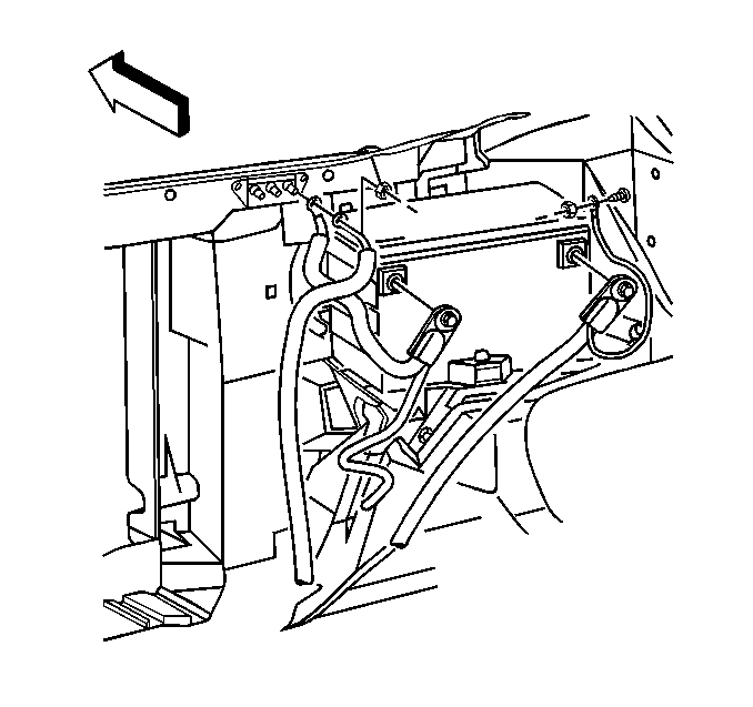
- Disconnect the battery negative cable. Refer to Battery Negative Cable Disconnection and Connection in Engine Electrical.
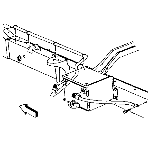
- Disconnect the battery negative cable from the auxiliary battery terminal. Refer to Auxiliary Battery Negative Cable Replacement in Engine Electrical.
- Drain the coolant from the radiator. Refer to Cooling System Draining and Filling .
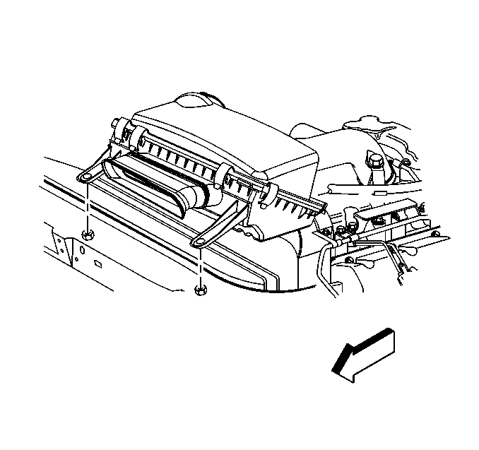
- Remove the air cleaner assembly from the vehicle. Refer to Air Cleaner Assembly Replacement in Engine Controls.
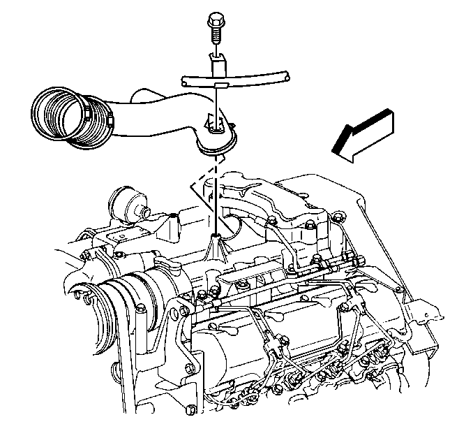
- Remove the air intake duct from the turbocharger.
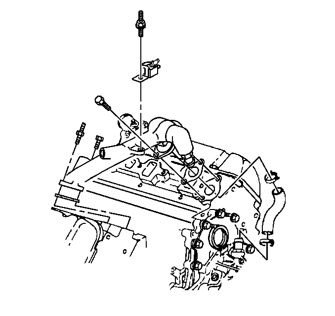
- Remove the nut securing the dipstick tubes at the thermostat housing.
- Remove the stud securing the fuel bleed valve at the thermostat housing.
- Remove the A/C compressor. Refer to Air Conditioning Compressor Replacement in HVAC.
- Disconnect the coolant temperature sensor electrical connector.
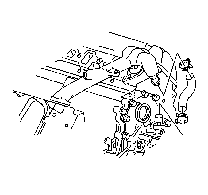
- Disconnect the heater hose at the thermostat housing crossover.
- Disconnect the by-pass hose at the thermostat housing crossover.
- Disconnect the upper radiator hose at the thermostat housing crossover.
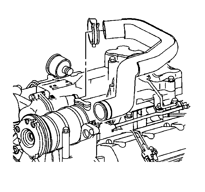
- Remove the studs and bolts securing the thermostat housing crossover to the engine.
- Remove the thermostat housing crossover.
- Clean the thermostat housing crossover sealing surfaces.
Caution: Unless directed otherwise, the ignition and start switch must be in the OFF or LOCK position, and all electrical loads must be OFF before servicing any electrical component. Disconnect the negative battery cable to prevent an electrical spark should a tool or equipment come in contact with an exposed electrical terminal. Failure to follow these precautions may result in personal injury and/or damage to the vehicle or its components.
Installation Procedure
- Install the new gaskets.
- Install the thermostat housing crossover.
- Install the studs and bolts retaining the thermostat housing crossover to the engine.
- Connect the upper radiator hose to the thermostat housing crossover.
- Connect the by-pass hose to the thermostat housing crossover.
- Connect the heater hose to the thermostat housing crossover.
- Connect the electrical connector to the coolant temperature sensor.
- Install the A/C compressor. Refer to Air Conditioning Compressor Replacement in HVAC.
- Install the stud in order to secure the fuel bleed valve at the thermostat housing.
- Install the nut in order to secure the dipstick tubes at the thermostat housing.
- Connect the battery negative cable to the auxiliary battery terminal. Refer to Auxiliary Battery Negative Cable Replacement in Engine Electrical.
- Refill the engine cooling system. Refer to Cooling System Draining and Filling in Engine Cooling.
- Bleed the air from the engine cooling system by the following:
- Install the air intake duct to the turbocharger.
- Install the air cleaner assembly in the vehicle. Refer to Air Cleaner Assembly Replacement in Engine Controls.
- Inspect the system for coolant leaks.

Tighten
Tighten the bolts and studs to 47 N·m (35 lb ft).


Connect the battery negative cable to the battery terminal. Refer to Battery Negative Cable Disconnection and Connection in Engine Electrical.
| 14.1. | Remove the cap from the surge tank. |
| 14.2. | Remove the bleed screw (slotted) from the top of the thermostat housing. |
| 14.3. | Pour anti-freeze into the surge tank, and watch for a of anti-freeze from the bleed screw. |
| 14.4. | When a constant flow of anti-freeze is reached, closed the bleed screw at the top of the thermostat housing. |
| 14.5. | Continue to fill the surge tank to the proper level. |
| 14.6. | Install the cap on the surge tank. |


