Tools Required
Removal Procedure
- Raise the vehicle. Refer to
Lifting and Jacking the Vehicle
in General Information.
- Lower the transmission if needed for clearance. Refer to
Transmission Replacement
.
- Install the
J 29714-A
Servo Cover Depressor.
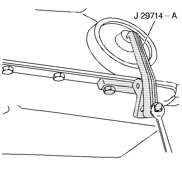
- Tighten the bolt in order to compress the servo cover.
- Remove the servo cover retaining ring.
- Remove the
J 29714-A
Servo Cover Depressor.
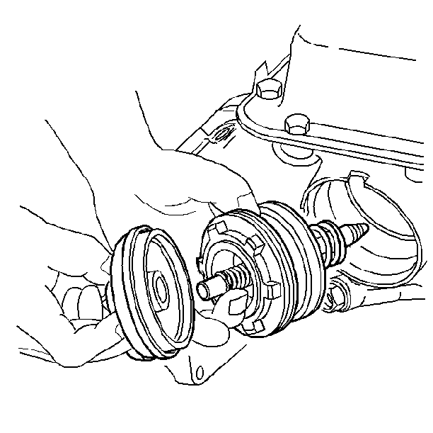
- Remove the servo cover and the O-ring seal. If the servo cover seems to be hung up on the seal, cut and remove the O-ring
seal before removing the cover.
- Remove the 2-4 servo assembly.
Disassembly Procedure
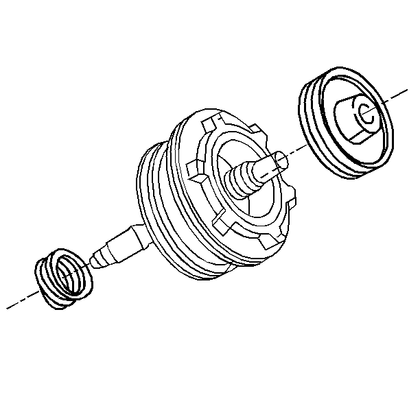
- Remove the following parts:
| • | The servo return spring |
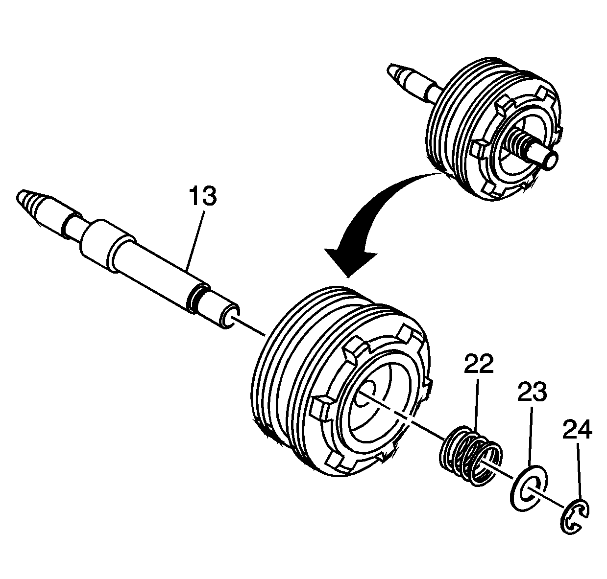
- Remove the following parts:
| • | The 2nd apply piston pin |
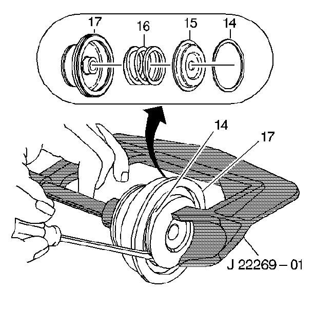
- Install the
J 22269-01
in order to compress the second apply
piston.
- Remove the second apply piston retaining ring.
- Remove the servo cushion spring retainer and the servo cushion spring.
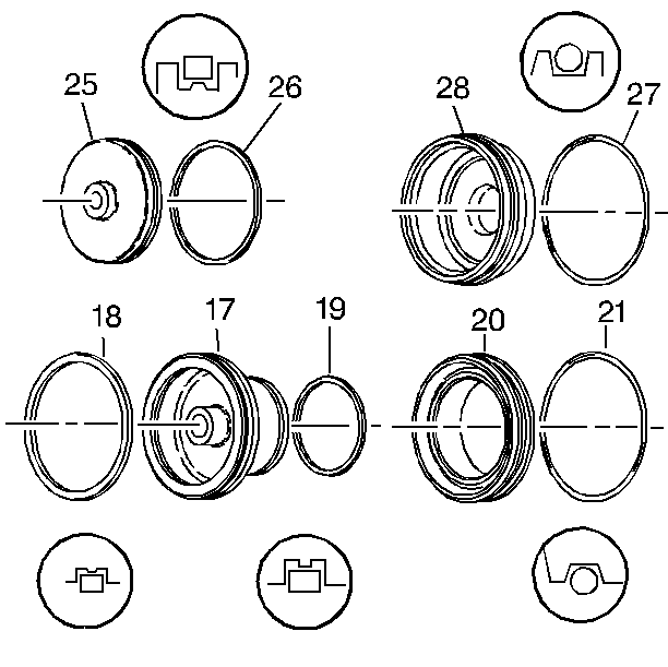
- Remove the seals from the cover, the housing, and the pistons.
Important: Check the case servo bore for damage and sharp edges.
- Clean all the parts using solvent.
- Air dry all the parts.
- Inspect the pistons for porosity and damage.
- Inspect the seal grooves for damage.
- Inspect the cover for porosity and damage.
- Inspect for nicks, cuts, and binding in the seal grooves. If damage is found, check for the cause of the damage.
- Inspect the springs for kinks and bending.
- Inspect the pin for wear and burrs.
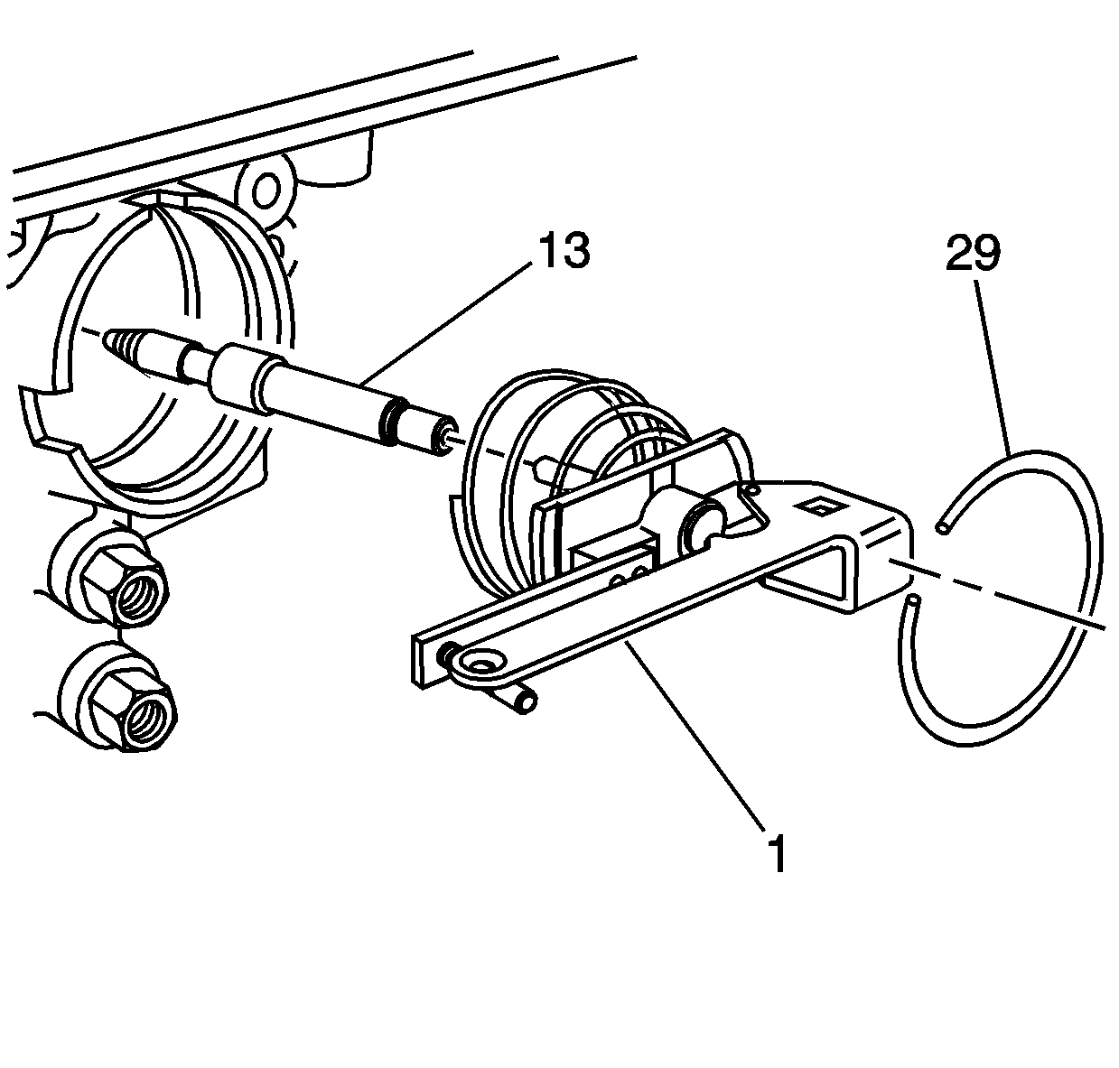
- Install the band apply pin and the
J 33037
.Band Apply
Pin Tool.
- Install the servo cover retaining ring to secure the tool.
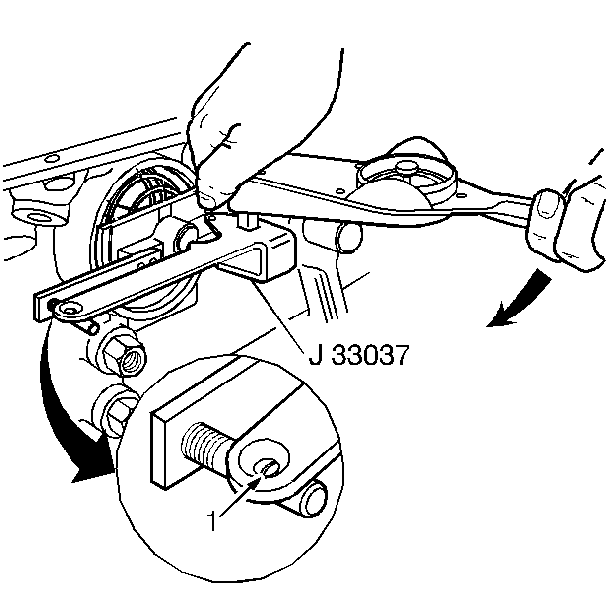
- Apply 11 N·m (98 lb in) torque. If the white line appears in the gauge slot, the pin length is correct.
- If the white line is not seen in the slot, replace the pin using the following pin identification:
| • | One groove, pin length 65.82--66.12 mm (2.59--2.60 in) |
| • | Two grooves, pin length 67.23--67.53 mm (2.65--2.66 in) |
| • | No grooves, pin length 68.64--68.94 mm (2.70--2.71 in) |
- Remove the pin and the
J 33037
Band Apply Pin Tool.
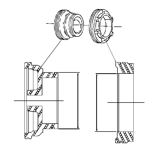
- Check the 2nd apply piston and the housing dimension.
- Measure the piston (25) dimension (1)
- Measure the housing (22) dimension (2)
- Check the table for the transmission and piston/housing specifications. Refer to
2-4 Band Servo Piston Pin Selection
.
Assembly Procedure

- Install new seals on all the 2-4 servo pistons and the cover.

- Install the servo cushion spring and the cushion spring retainer in the 2nd apply piston. Use the
J 22269-01
in order to compress the second apply piston.
- Install the second apply piston retaining ring.

- Install the following parts:
| • | The 2nd apply piston pin |

- Install the following parts:
| • | The servo return spring |
Installation Procedure

- Install the 2-4 servo assembly into the 2-4 servo bore.
- Install the
J 29714-A
Servo Cover Compressor.

- Tighten the bolt in order to compress the servo cover.
- Install the servo cover retaining ring.
- Remove the
J 29714-A
from the oil pan flange.
Notice: Refer to Fastener Notice in the Preface section.
- Install the oil pan bolt.
Tighten
Tighten the oil pan bolt to 11 N·m (97 lb in).
- Lower the vehicle.
- Check the automatic transmission fluid level and add new automatic transmission fluid as needed. Refer to
Transmission Fluid Check
and to
Fluid Capacity Specifications
.
Important: It is recommended that the transmission adaptive pressure (TAP) information be reset.
Resetting the TAP values using a scan tool will erase all learned values in all cells. As a result, the ECM, PCM or TCM
will need to relearn the TAP values. Transmission performance may be affected as new TAP values are learned,
- Reset the TAP values. Refer to
Adapt Function
.


