For 1990-2009 cars only
Tools Required
J 25025 -5 Guide Pin
Removal Procedure
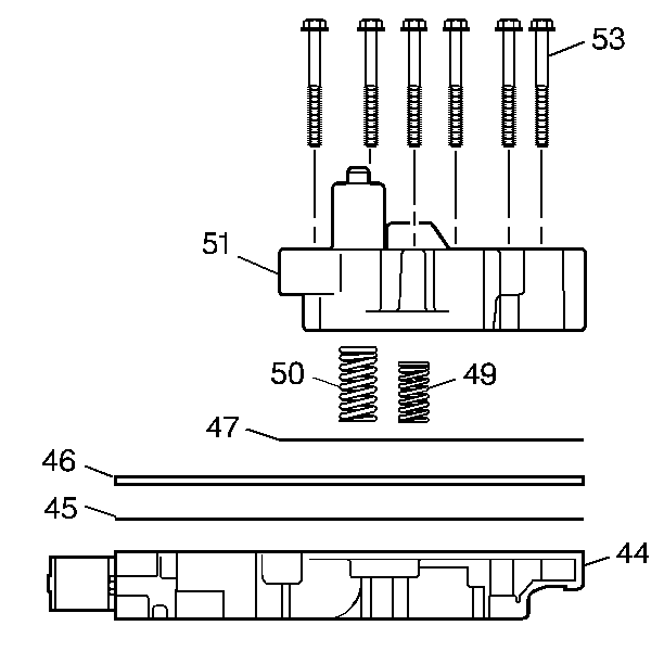
- Remove the 3rd and 4th clutch accumulator housing bolts (53).
- Remove the 3rd and 4th clutch accumulator housing (51).
- Remove the accumulator housing gasket (47). The accumulator housing gasket may be stuck to the spacer plate (46).
- Remove the 3rd clutch accumulator piston spring (50).
- Remove the 4th clutch accumulator piston spring (49).
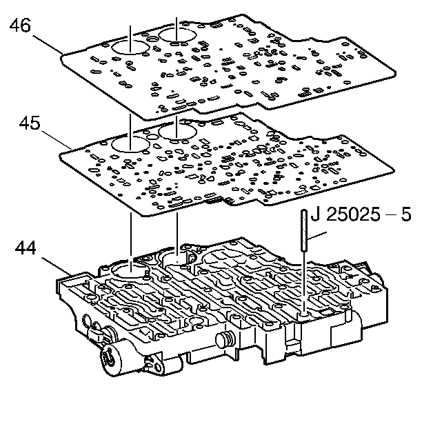
- Remove the control valve body spacer plate (46).
- Remove the control valve assembly to spacer plate gasket (45) from the spacer plate (46).

Installation Procedure
- Install the J 25025 into the control valve body bolt hole where the manual shaft detent roller and spring assembly is mounted.
- Install the control valve body gasket (45).
- Install the control valve body spacer plate (46).
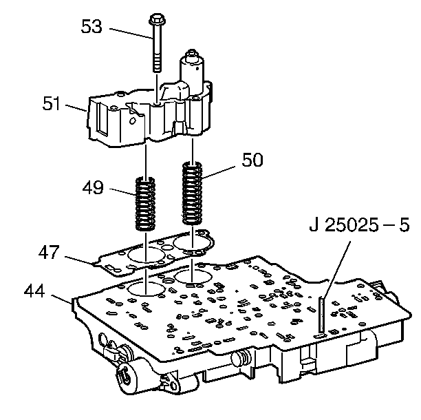
- Install the third and fourth clutch accumulator housing gasket (47).
- Install the third clutch accumulator piston spring (50). This spring is the longer of the two springs.
- Install the fourth clutch accumulator piston spring (49).
- Install the third and fourth clutch accumulator housing assembly (51) onto the control valve body assembly (44).
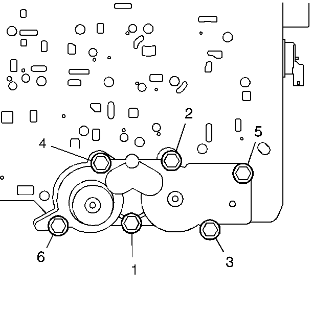
- Install the six accumulator housing bolts (53). Start the bolts finger tight and work towards the opposite end.
- Tighten the accumulator housing bolts sequentially.
- Remove the J 25025 -5.
- Reset the TAP values. Refer to Adapt Function .


Notice: Refer to Fastener Notice in the Preface section.

Tighten
Tighten the accumulator housing bolts sequentially to 11 N·m (97 lb in).
Important: It is recommended that transmission adaptive pressure (TAP) information be reset.
Resetting the TAP values using a scan tool will erase all learned values in all cells. As a result, The ECM, PCM or TCM will need to relearn TAP values. Transmission performance may be affected as new TAP values are learned.