For 1990-2009 cars only
Removal Procedure
- Remove all related panels and components, including jack stowaway mount in right rear corner of vehicle.
- Visually inspect and restore as much of the damage as possible to factory specifications.
- Remove the following as necessary:
- Locate, mark, and drill out factory welds necessary to remove the extension panel.
- Loosen all body to frame mount bolts, remove all but two in the radiator core support and the two front body bolts.
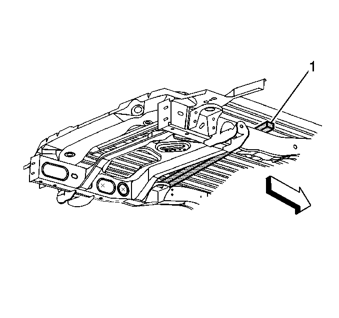
- Lift body off the frame, place 4x4 wood blocks (1) to support the body.
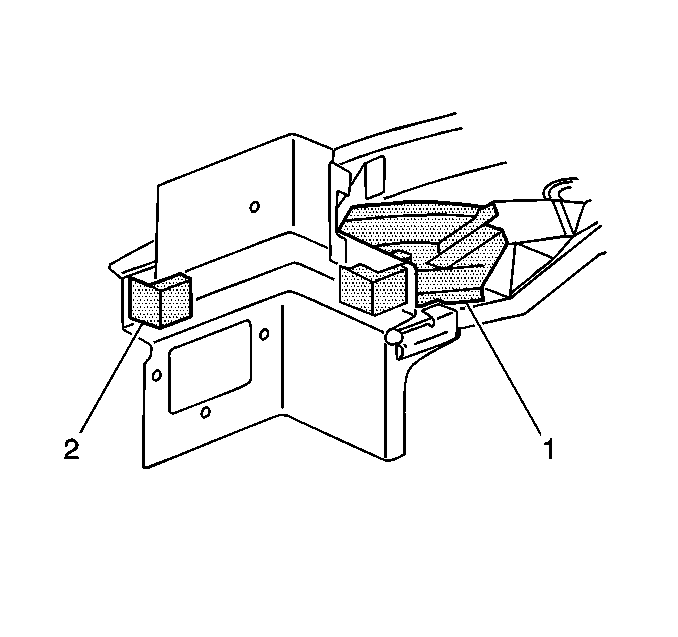
- Locate, mark, and drill out welds to remove the body mount anchor plates (1) and the floor panel reinforcement.
- Remove the foam air baffles (2) from the right and left floor extensions, these need to be reinstalled during assembly.
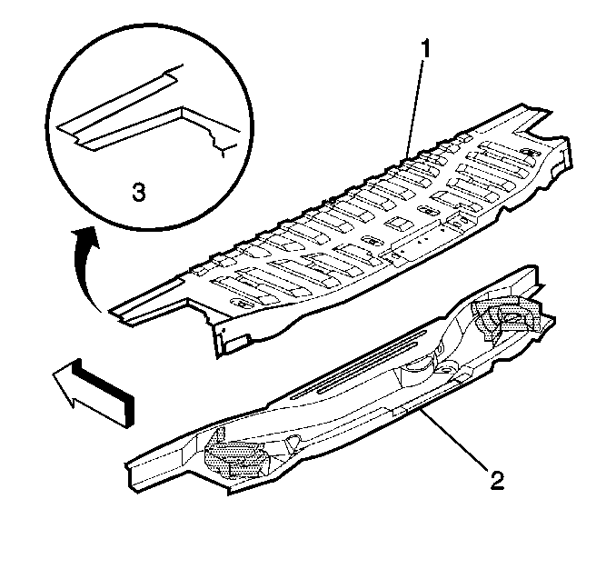
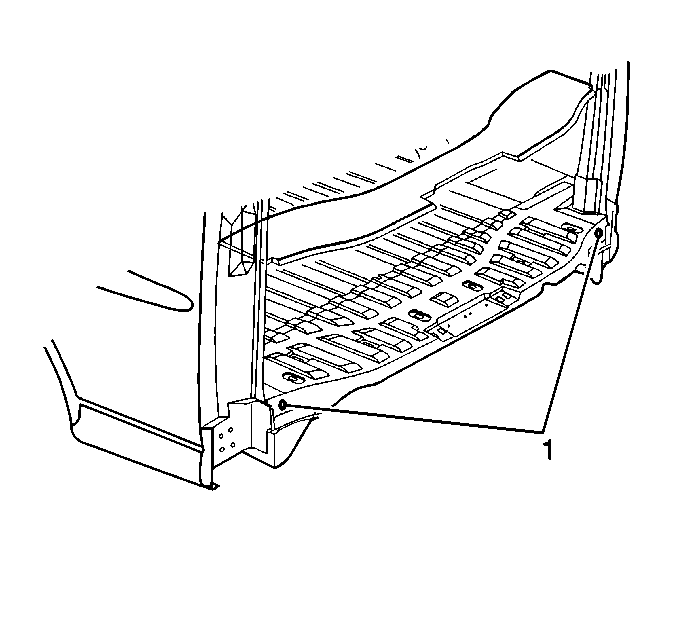
Important: The floor rear extension panel is serviced as a single component (1). The reinforcement structure for the floor panel is a separate part (2) and can only be serviced separately. In most, cases, this reinforcement will need to be replaced in the event the floor panel extension is to be replaced.
| • | Sealers |
| • | Sound deadeners |
| • | Anti-corrosion materials |
| Important: The rear corners of the original panel (3) must be cut to remove the panel from the vehicle. |
Important: If a rear door hinge pillar inner reinforcement is to be replaced it is not necessary to perform step 5.
Installation Procedure
- Drill holes for plug welding as necessary to install the service panels.
- Clean and prepare all mating surfaces as necessary.
- Locate reinforcement and body anchor panels. Use three-dimensional measuring equipment.
- Plug weld as necessary.
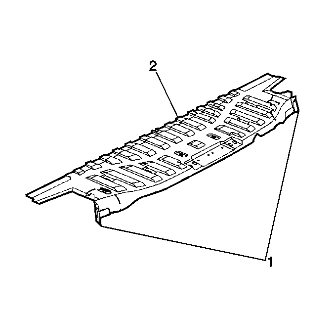
- Cut and bend each side of the floor panel extension (1).
- Place the front edge of the extension (2) panel in position.
- Bring the rear of the service part into place and straighten the bent tabs.
- Check for proper fit and alignment.
- Weld accordingly, including cuts made for installation.
- Lower body to frame and reattach body to frame mounts, torque bolts to 85 N·m (63 lbs ft).
- Clean and prepare welded surfaces.
- Prime with two-part catalyzed primer.
- Drill appropriate size holes to install two-part expanding foam in the floor extension (1).
- Seal holes with a suitable plug (1).
- Apply sealers and anti-corrosion materials as necessary.
- Install all related panels and components.
Important: Do not combine paint systems. Refer to manufacturers recommendations.
