For 1990-2009 cars only
Tools Required
J 23742 Ball Joint Seperator
Removal Procedure
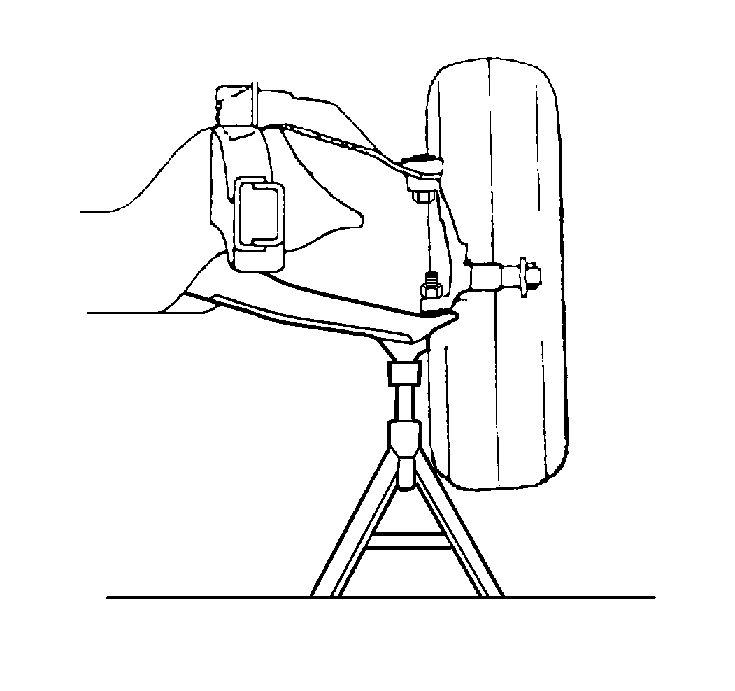
- Raise the vehicle. Place suitable safety stands under the control arms.
- Remove the tire and wheel assembly. Refer to Tire and Wheel Removal and Installation in Tires and Wheels.
- Disconnect the tie rod from the steering knuckle. Refer to Tie Rod Replacement in Steering Linkage.
- Remove the front brake caliper. Refer to Brake Caliper Replacement in Disc Brakes.
- Remove the hub/rotor. Refer to Front Wheel Hub, Bearing, and Seal Replacement .
- Remove the steering knuckle seal. Do not damage the seal.
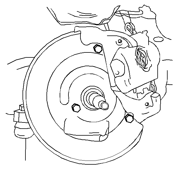
- Remove the three bolts that attach the splash shield to the knuckle.
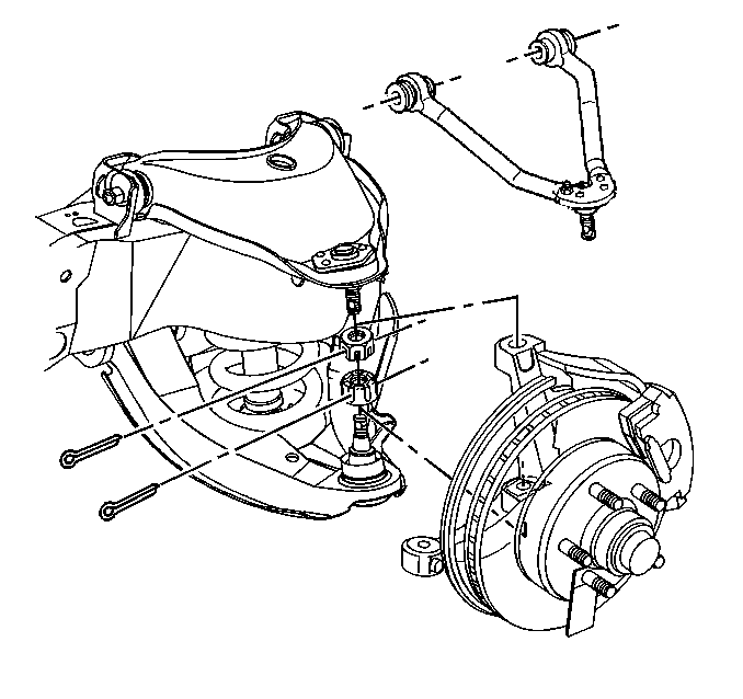
- Using the J 23742 separate the upper and the lower ball joint studs from the steering knuckle. Refer to Upper Control Arm Ball Joint Replacement or Lower Control Arm Ball Joint Replacement .
- Remove the wheel speed sensor from the steering knuckle. Refer to Wheel Speed Sensor Replacement in Antilock Brake System.
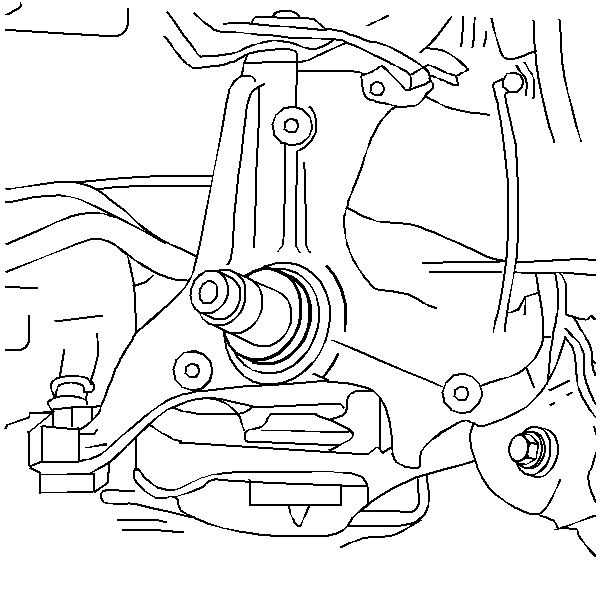
- Remove the knuckle.

Notice: Support the caliper with a piece of wire to prevent damage to the brake line.


| 10.1. | Clean the steering knuckle. |
| 10.2. | Inspect the steering knuckle tapered hole. If this tapered hole is out-of-round, deformed, or damaged, replace the knuckle. |
Installation Procedure
- Install the wheel speed sensor in the steering knuckle. Refer to Wheel Speed Sensor Replacement in Antilock Brake System.
- Install the upper and lower ball joints into the steering knuckle. Refer to Lower Control Arm Ball Joint Replacement or Upper Control Arm Ball Joint Replacement .
- Install the steering knuckle seal.
- Install the splash shield to the steering knuckle.
- Install the bolts to the splash shield.
- Install the tie rod end into the knuckle and install the tie rod end retaining nut. Refer to Tie Rod Replacement in Steering Linkage.
- Install the hub/rotor. Refer to Front Wheel Hub, Bearing, and Seal Replacement
- Adjust the wheel bearings. Refer to Wheel Bearing Adjustment
- Install the front brake caliper. Refer to Brake Caliper Replacement in Disc Brakes.
- Install the tire and wheel assembly. Refer to Tire and Wheel Removal and Installation in Tires and Wheels.
- Remove the safety stands.
- Lower the vehicle.
- Check the front wheel alignment. Refer to Wheel Alignment Specifications in Wheel Alignment.


Tighten
Tighten the nuts to 24 N·m (18 lb ft).
