Tools Required
J 8001 Dial Indicator
Set
Important:
| • | The vehicle must rest on a level surface. |
| • | The vehicle must be stable. Do not rock the vehicle on the floor
stands. |
| • | The upper control arm bumper must not contact the frame. |

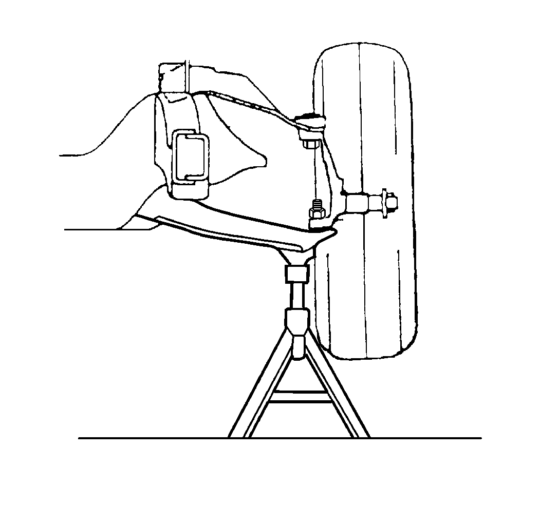
- Raise the vehicle. Support
the lower control arm with a floor stand or jack, as far outboard as possible,
near the ball joint.
- Wipe the ball joints clean. Check the seals for cuts or tears.
- Adjust the wheel bearings. Refer to
Wheel Bearing Adjustment

- Check the ball joints
for horizontal looseness.
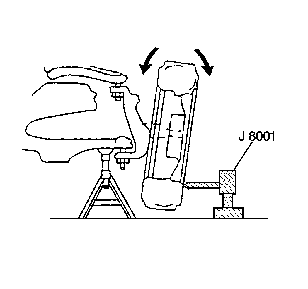
| • | Position the dial indicator against the lowest outboard point
on the wheel rim. |
| • | Rock the wheel in and out while reading the dial indicator. This
shows horizontal looseness in both joints. |
| • | The indicator reading should be no more than 3.18 mm (0.125 in).
If the reading is too high, check the lower ball joint for vertical looseness. |

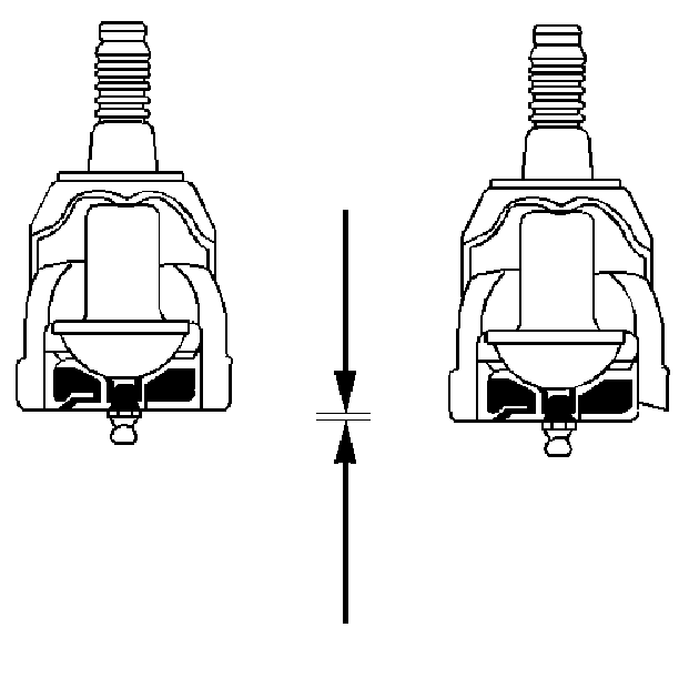
- Check the ball joints
for vertical looseness.
| 5.1. | Position the dial indicator against the spindle to show vertical
movement. |
| 5.2. | Pry between the lower control arm and the outer race while reading
the dial indicator. This shows vertical looseness in the ball joints. |


