Removal Procedures
- Disconnect the battery negative cables from the batteries. Refer to Battery Negative Cable Disconnection and Connection in Engine Electrical.
- Remove the left side lower intake manifold in order to access the fuel injection pipes. Refer to Lower Intake Manifold Replacement .
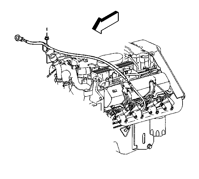
- Remove the shift cable bracket and shield.
- Remove the fuel injection lines and clips for the fuel injection nozzles. Refer to Fuel Injection Line Replacement in Engine Controls-6.5L (L65).
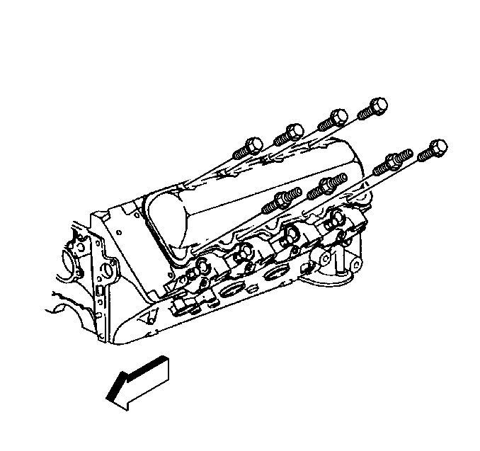
- Remove the valve rocker arm cover bolts.
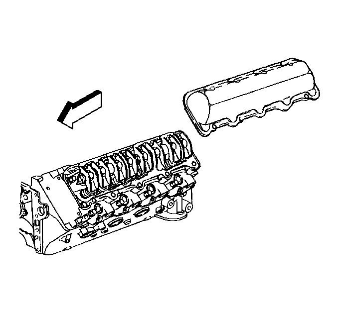
- Remove the valve rocker arm cover from the cylinder head.
- Clean the sealing surfaces on the valve rocker arm cover and the cylinder head.

Important: Do not bend the fuel injector lines in order to ease in the removal of the valve rocker arm cover.


Notice: Prying on the valve rocker arm cover may cause damage to the sealing surfaces. Use a block of wood against the side of the valve rocker arm cover and strike with a hammer in a sideways direction to shear the RTV sealant.
Installation Procedure
Notice: Do not allow the RTV sealant to enter any blind threaded hole. RTV sealant that is allowed to enter a blind threaded hole can cause hydraulic lock of the fastener when the fastener is tightened. Hydraulic lock of a fastener can lead to damage to the fastener and/or the components. Hydraulic lock of a fastener can also prevent the proper clamping loads to be obtained when the fastener is tightened. Improper clamping loads can prevent proper sealing of the components allowing leakage to occur. Preventing proper fastener tightening can allow the components to loosen or separate leading to extensive engine damage.
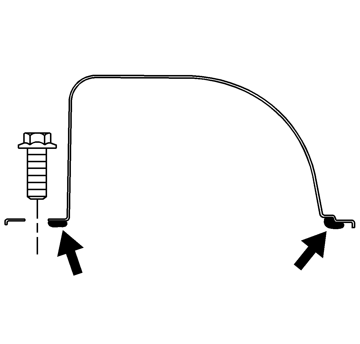
- Apply the RTV sealant GM P/N 12346286 to the valve rocker arm covers.
- Install the valve rocker arm cover to the cylinder head.
- Install the valve rocker arm cover bolts.
- Install the fuel injection lines and clips. Refer to Fuel Injection Line Replacement in Engine Controls-6.5L (L65).
- Install the shift cable bracket and shield.
- Install the lower intake manifold. Refer to Lower Intake Manifold Replacement .
- Connect the battery negative cables from the batteries. Refer to Battery Negative Cable Disconnection and Connection in Engine Electrical.

Important: Apply a 5-8 mm (3/16-5/16 in) bead of RTV sealant to the valve rocker arm cover. The sealant should be applied such as that it follows and overlaps the stepped ridge. This will distribute the RTV on both the upper and lower levels of the step. When the valve rocker arm cover is fastened to the cylinder head, the RTV should flow on both the valve rocker arm cover and the cylinder head sealing surfaces. The sealer must be wet to the touch when the bolts are tightened to specifications.


Notice: Use the correct fastener in the correct location. Replacement fasteners must be the correct part number for that application. Fasteners requiring replacement or fasteners requiring the use of thread locking compound or sealant are identified in the service procedure. Do not use paints, lubricants, or corrosion inhibitors on fasteners or fastener joint surfaces unless specified. These coatings affect fastener torque and joint clamping force and may damage the fastener. Use the correct tightening sequence and specifications when installing fasteners in order to avoid damage to parts and systems.
Tighten
Tighten the cover bolts to 27 N·m (20 lb ft).
Tighten
Tighten the bracket bolts to 25 N·m (18 lb ft).
