Fuel Tank Replacement Passenger/Cargo
Tools Required
J 36608 Fuel Sender Tool
Removal Procedure
- Disconnect the negative battery cables.
- Drain the fuel from the tank. Refer to Fuel Tank Draining .
- Raise the vehicle. Refer to Lifting and Jacking the Vehicle in General Information.
- Remove the off-road shield, if applicable.
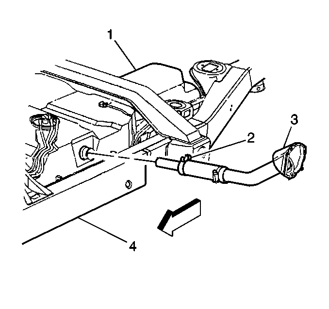
- Loosen the filler neck hose clamp (2) at the fuel tank (1).
- Disconnect the filler neck hose (3) from the fuel tank.
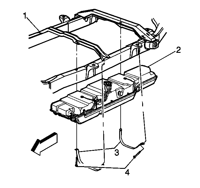
- Support the fuel tank.
- Remove the fuel tank bolts (4), straps (3) and the insulator strips, if applicable.
- Slightly lower the fuel tank (2) and the fuel tank shield.
- Disconnect the fuel feed and the vapor hoses.
- Disconnect the electrical connections at the fuel sender assembly.
- Lower the fuel tank and the fuel tank shield.
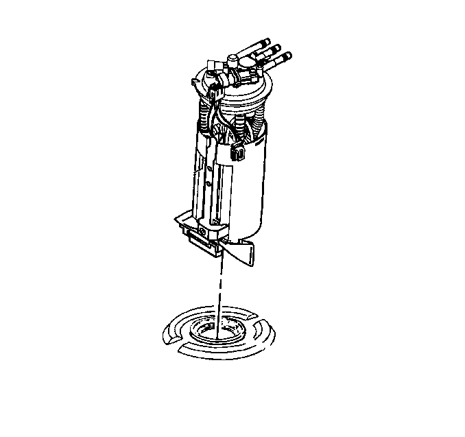
- Use the J 36608 in order to remove the fuel sender assembly and the seal ring. Discard the old seal ring.
- Purge the tank, if the tank is being repaired.
Caution: Unless directed otherwise, the ignition and start switch must be in the OFF or LOCK position, and all electrical loads must be OFF before servicing any electrical component. Disconnect the negative battery cable to prevent an electrical spark should a tool or equipment come in contact with an exposed electrical terminal. Failure to follow these precautions may result in personal injury and/or damage to the vehicle or its components.
Installation Procedure
- Install a new seal ring.
- Slightly raise the fuel tank and the fuel tank shield.
- Use the J 36608 in order to install the fuel sender assembly .
- Connect the fuel feed and the vapor hoses.
- Connect the electrical connector to the fuel sender assembly.
- Raise the fuel tank fully.
- Install the fuel filler neck (3) to the fuel tank (1).
- Install the clamp (2).
- Install the fuel tank brackets (3) with the insulator strips in place.
- Install the fuel tank off-road shield, if applicable.
- Lower the vehicle.
- Replenish the fuel in the fuel tank (2).
- Install the fuel tank filler cap.
- Connect the batteries. If a memory retention device was not used, reset (to the extent possible) all of the devices that lost their memory after the battery was disconnected.
- Inspect for leaks with the following procedure:


Notice: Use the correct fastener in the correct location. Replacement fasteners must be the correct part number for that application. Fasteners requiring replacement or fasteners requiring the use of thread locking compound or sealant are identified in the service procedure. Do not use paints, lubricants, or corrosion inhibitors on fasteners or fastener joint surfaces unless specified. These coatings affect fastener torque and joint clamping force and may damage the fastener. Use the correct tightening sequence and specifications when installing fasteners in order to avoid damage to parts and systems.
Tighten
Tighten the clamp to 2.5 N·m (22 lb in).

Notice: Tighten the strap fasteners by steps, alternating between the fasteners, until the specified torque is reached. A failure to tighten the strap fasteners as specified will cause the bottom of the tank to flex upward. This will result in the fuel gauge indicating that there is fuel remaining in the tank when the tank is empty.
Tighten
Tighten the fuel tank bolts (4) to 45 N·m (33 lb ft).
| 15.1. | Turn ON the ignition for 2 seconds. |
| 15.2. | Turn OFF the ignition for 10 seconds. |
| 15.3. | Turn ON the ignition. |
| 15.4. | Inspect for any fuel leaks. |
Fuel Tank Replacement Commercial/RV
Tools Required
J 36608 Fuel Sender Tool
Removal Procedure
- Drain the fuel from the tank. Refer to Fuel Tank Draining .
- Raise the vehicle. Refer to Lifting and Jacking the Vehicle in General Information. This must be done with a frame hoist to allow the rear suspension to hang.
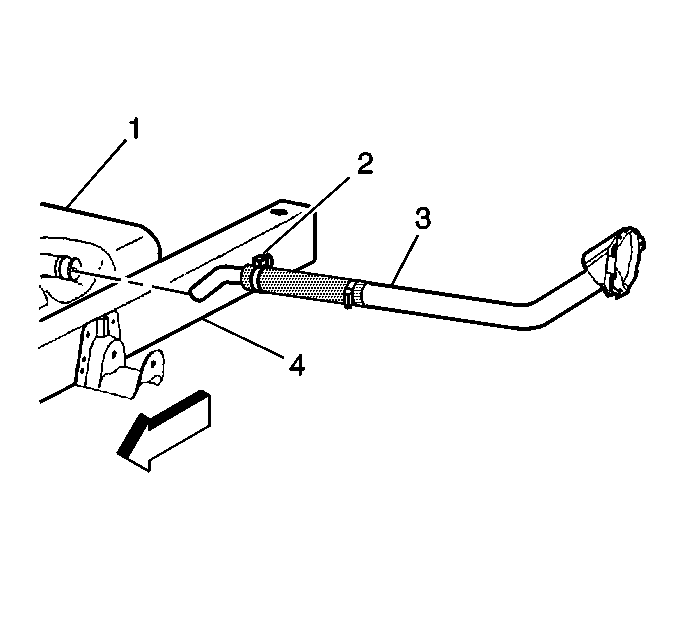
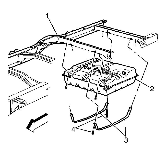
- Remove the filler neck hose (3) and the vent hose from the fuel tank (1).
- Support the fuel tank.
- Remove the fuel tank bolts (4) and straps (3).
- Lower the fuel tank (2) and the fuel tank shield.
- Disconnect the fuel feed and the vapor hoses. Refer to Plastic Collar Quick Connect Fitting Service .
- Disconnect the electrical connections at the fuel sender assembly.
- Remove the fuel tank.
- Use the J 36608 in order to remove the fuel sender assembly and the seal ring. Discard the old seal ring.
- Purge the tank if the tank is being repaired.

Installation Procedure
- Install a new seal ring.
- Use the J 36608 in order to install the fuel sender assembly.
- Raise the tank slightly.
- Connect the fuel feed and vapor hoses. Refer to Plastic Collar Quick Connect Fitting Service .
- Connect the electrical connector to the fuel sender assembly.
- Raise the fuel tank (2) fully.
- Install the fuel tank shield.
- Install the fuel tank brackets (3) with the insulator strips in place.
- Install the fuel filler neck (3) to the fuel tank (1).
- Lower the vehicle.
- Replenish the fuel in the fuel tank.
- Install the fuel tank filler cap.
- Connect the negative battery cable. If a memory retention device was not used, reset (to the extent possible) all of the devices that lost their memory after the battery was disconnected.
- Inspect for leaks with the following procedure:


Notice: Use the correct fastener in the correct location. Replacement fasteners must be the correct part number for that application. Fasteners requiring replacement or fasteners requiring the use of thread locking compound or sealant are identified in the service procedure. Do not use paints, lubricants, or corrosion inhibitors on fasteners or fastener joint surfaces unless specified. These coatings affect fastener torque and joint clamping force and may damage the fastener. Use the correct tightening sequence and specifications when installing fasteners in order to avoid damage to parts and systems.
Notice: Tighten the strap fasteners by steps, alternating between the fasteners, until the specified torque is reached. A failure to tighten the strap fasteners as specified will cause the bottom of the tank to flex upward. This will result in the fuel gauge indicating that there is fuel remaining in the tank when the tank is empty.
Tighten
Tighten the fuel tank bolts (4) to 12 N·m (106 lb in).

| 14.1. | Turn ON the ignition for 2 seconds. |
| 14.2. | Turn OFF the ignition for 10 seconds. |
| 14.3. | Turn ON the ignition. |
| 14.4. | Inspect for any fuel leaks. |
