Removal Procedure
Important: Note the identification code on the valve. Have the proper code when ordering a replacement valve.
- Raise the vehicle and properly support it with safety stands.
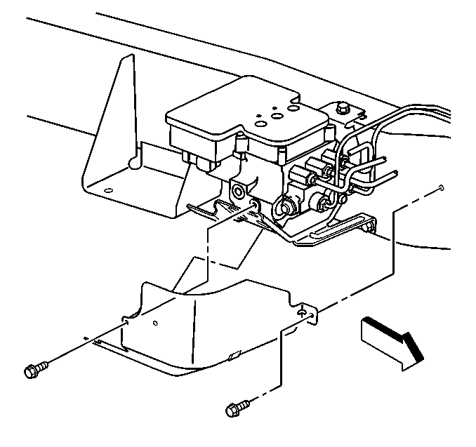
- Remove the retaining bolts from the shield.
- Remove the shield.
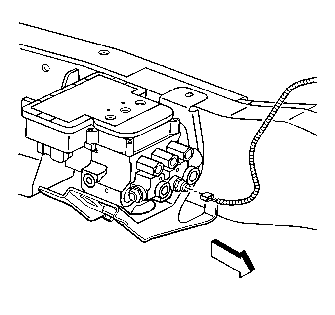
- Disconnect the 2-way electrical connector from the combination valve.
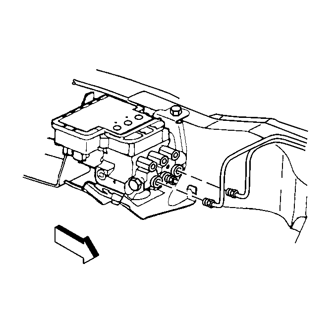
- Disconnect the front and rear brake pipes from the combination valve.
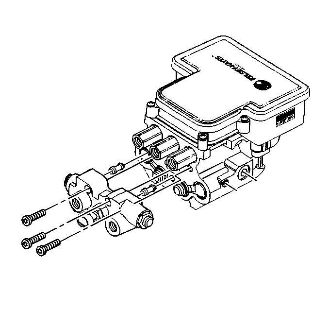
- Remove the Allen bolts that fasten the combination valve to the BPMV.
- Remove the combination valve from the BPMV.
- Install the transfer tubes to the valve.


Installation Procedure
Important:
• Do not reuse the old transfer tubes. Always install new transfer
tubes with a new combination valve. • Ensure that the replacement combination valve has the same pin
punched identification code as the old part.
- Install the transfer tubes into the combination valve until the transfer tubes are fully seated.
- Install the combination valve to the BPMV.
- Install the Allen bolts to the combination valve and the BPMV.
- Connect the front and rear brake pipes to the combination valve.
- Connect the 2-way electrical connector to the combination valve.
- Install the shield to the vehicle.
- Install the retaining bolts of the shield.
- Bleed the brake hydraulic system. Refer to Hydraulic Brake System Bleeding .

Notice: Use the correct fastener in the correct location. Replacement fasteners must be the correct part number for that application. Fasteners requiring replacement or fasteners requiring the use of thread locking compound or sealant are identified in the service procedure. Do not use paints, lubricants, or corrosion inhibitors on fasteners or fastener joint surfaces unless specified. These coatings affect fastener torque and joint clamping force and may damage the fastener. Use the correct tightening sequence and specifications when installing fasteners in order to avoid damage to parts and systems.
Tighten
| • | Tighten the Allen bolts of the combination valve to 8 N·m (6 lb ft). |
| • | Tighten the Allen bolts of the combination valve a second time to 16 N·m (12 lb ft). |

Tighten
Tighten the brake pipe fittings to the combination valve to 30 N·m
(22 lb ft).


Tighten
Tighten the retaining bolts of the shield to 12 N·m (8 lb ft).
Important: Make sure that the metering rod of the combination valve is depressed during bleeding.
