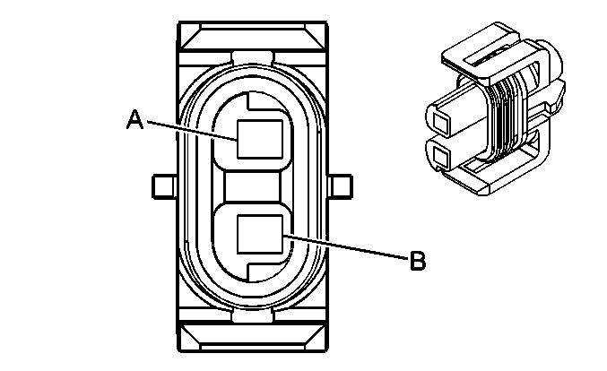
| Table 1: | A/C Compressor Clutch |
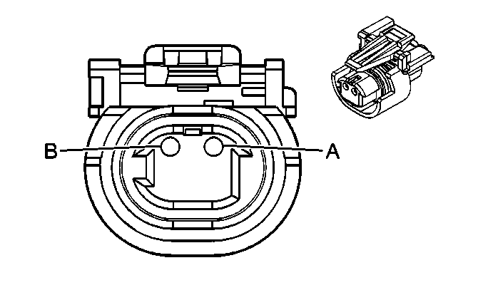
| Table 2: | A/C High Pressure Switch - Diesel |
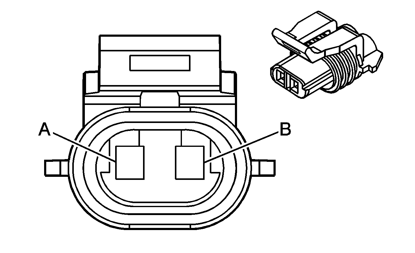
| Table 3: | A/C High Pressure Switch - Gas |
| Table 4: | A/C Low Pressure Switch - Diesel |
| Table 5: | A/C Low Pressure Switch - Gas |
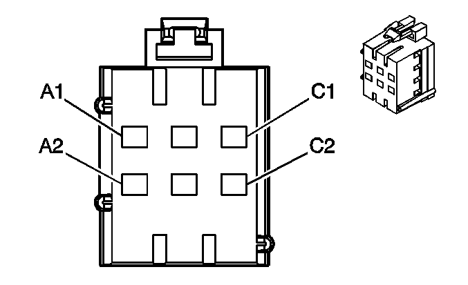
| Table 6: | Auxiliary Blower Motor Relay, Low/Medium/High Connectors |
| Table 7: | Auxiliary Blower Motor Resistor |
| Table 8: | Auxiliary Blower Motor Switch |
| Table 9: | Blower Motor |
| Table 10: | Blower Motor - Auxiliary |
| Table 11: | Blower Motor Resistor/Relay |
| Table 12: | Front Auxiliary Controller |
| Table 13: | HVAC Control Assembly C1 Connector |
| Table 14: | HVAC Control Assembly C2 Connector |
| Table 15: | HVAC Control Assembly C3 Connector |
| Table 16: | Rear Auxiliary HVAC Controller |
| Table 17: | Rear Auxiliary Mode Valve and Seal Assembly (Mode Door Motor) |
| Table 18: | Rear Auxiliary Temperature Valve Assembly (Temperature Door Motor) |
| |||||||
|---|---|---|---|---|---|---|---|
Connector Part Information |
| ||||||
Pin | Wire Color | Circuit No. | Function | ||||
A | BLK | 150 | Ground | ||||
B | DK GRN | 59 | A/C Compressor Clutch Supply Voltage | ||||
| |||||||
|---|---|---|---|---|---|---|---|
Connector Part Information |
| ||||||
Pin | Wire Color | Circuit No. | Function | ||||
A | DK GRN/WHT | 2523 | A/C Request Signal | ||||
B | DK GRN | 603 | A/C Low Pressure Switch Signal | ||||

| |||||||
|---|---|---|---|---|---|---|---|
Connector Part Information |
| ||||||
Pin | Wire Color | Circuit No. | Function | ||||
A | DK GRN/WHT | 2523 | A/C Request Signal | ||||
B | LT GRN | 66 | A/C Request Signal | ||||
| |||||||
|---|---|---|---|---|---|---|---|
Connector Part Information |
| ||||||
Pin | Wire Color | Circuit No. | Function | ||||
A | LT GRN | 66 | A/C Request Signal | ||||
B | DK GRN | 603 | A/C Low Pressure Switch Signal | ||||

| |||||||
|---|---|---|---|---|---|---|---|
Connector Part Information |
| ||||||
Pin | Wire Color | Circuit No. | Function | ||||
A | BLK | 150 | Ground - w/o L18 | ||||
A | DK GRN | 603 | A/C Low Pressure Switch Signal - w/L18 | ||||
B | DK GRN | 603 | A/C Low Pressure Switch Signal - w/o L18 | ||||
B | BLK | 150 | Ground - w/L18 | ||||
| |||||||
|---|---|---|---|---|---|---|---|
Connector Part Information |
| ||||||
Pin | Wire Color | Circuit No. | Function | ||||
A1 | WHT | 1924 | Auxiliary HVAC Switch Output (High) | ||||
A1 | RED | 1925 | Auxiliary HVAC Switch Output (Medium) | ||||
A1 | DK BLU | 1926 | Auxiliary HVAC Switch Output (Low) | ||||
A2 | YEL | 1172 | Auxiliary Blower Motor Feed (High) | ||||
A2 | LT BLU | 1072 | Auxiliary Blower Motor Feed (Medium) | ||||
A2 | YEL | 1176 | Auxiliary Blower Motor Feed (Low) | ||||
B1-B2 | -- | -- | Not Used | ||||
C1 | RED | 1542 | Fuse Output - Battery - Type II Fuse | ||||
C2 | BRN | 341 | Fuse Output - IGN 3 - Type III Fuse | ||||
| |||||||
|---|---|---|---|---|---|---|---|
Connector Part Information |
| ||||||
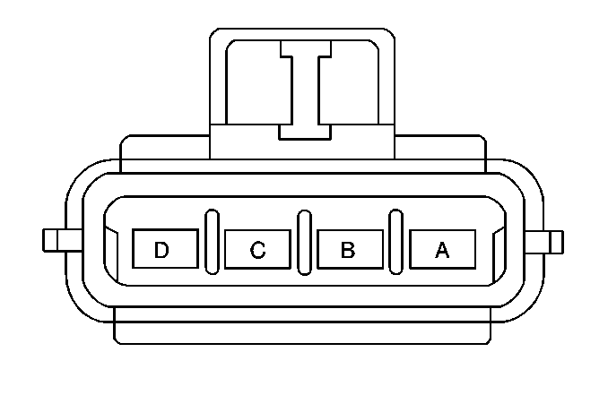
Pin | Wire Color | Circuit No. | Function | ||||
A | YEL | 1176 | Auxiliary Blower Motor Resistor Output (Low) | ||||
B | -- | -- | Not Used | ||||
C | LT BLU | 1072 | Auxiliary Blower Motor Resistor Output (Medium) | ||||
D | YEL | 1172 | Auxiliary Blower Motor Feed | ||||
| |||||||
|---|---|---|---|---|---|---|---|
Connector Part Information |
| ||||||
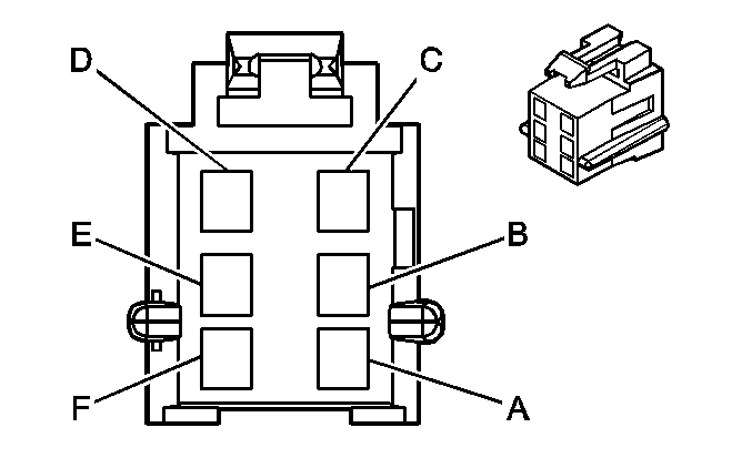
Pin | Wire Color | Circuit No. | Function | ||||
A | GRY | 8 | Instrument Panel Lamp Feed | ||||
B | BLK | 150 | Ground | ||||
C | -- | -- | Not Used | ||||
D | ORN | 52 | Blower Switch Output (High) | ||||
E | YEL | 60 | Blower Switch Output (Low) | ||||
F | TAN | 63 | Blower Switch Output (Medium 1) | ||||
| |||||||
|---|---|---|---|---|---|---|---|
Connector Part Information |
| ||||||
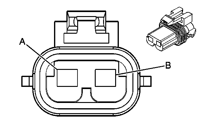
Pin | Wire Color | Circuit No. | Function | ||||
A | BLK | 150 | Ground | ||||
B | PPL | 65 | Blower Motor Supply Voltage | ||||

| |||||||
|---|---|---|---|---|---|---|---|
Connector Part Information |
| ||||||
Pin | Wire Color | Circuit No. | Function | ||||
A | BLK | 150 | Ground | ||||
B | YEL | 1172 | Auxiliary Blower Motor Feed | ||||
| |||||||
|---|---|---|---|---|---|---|---|
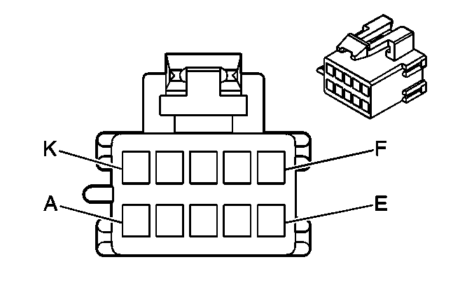
Connector Part Information |
| ||||||
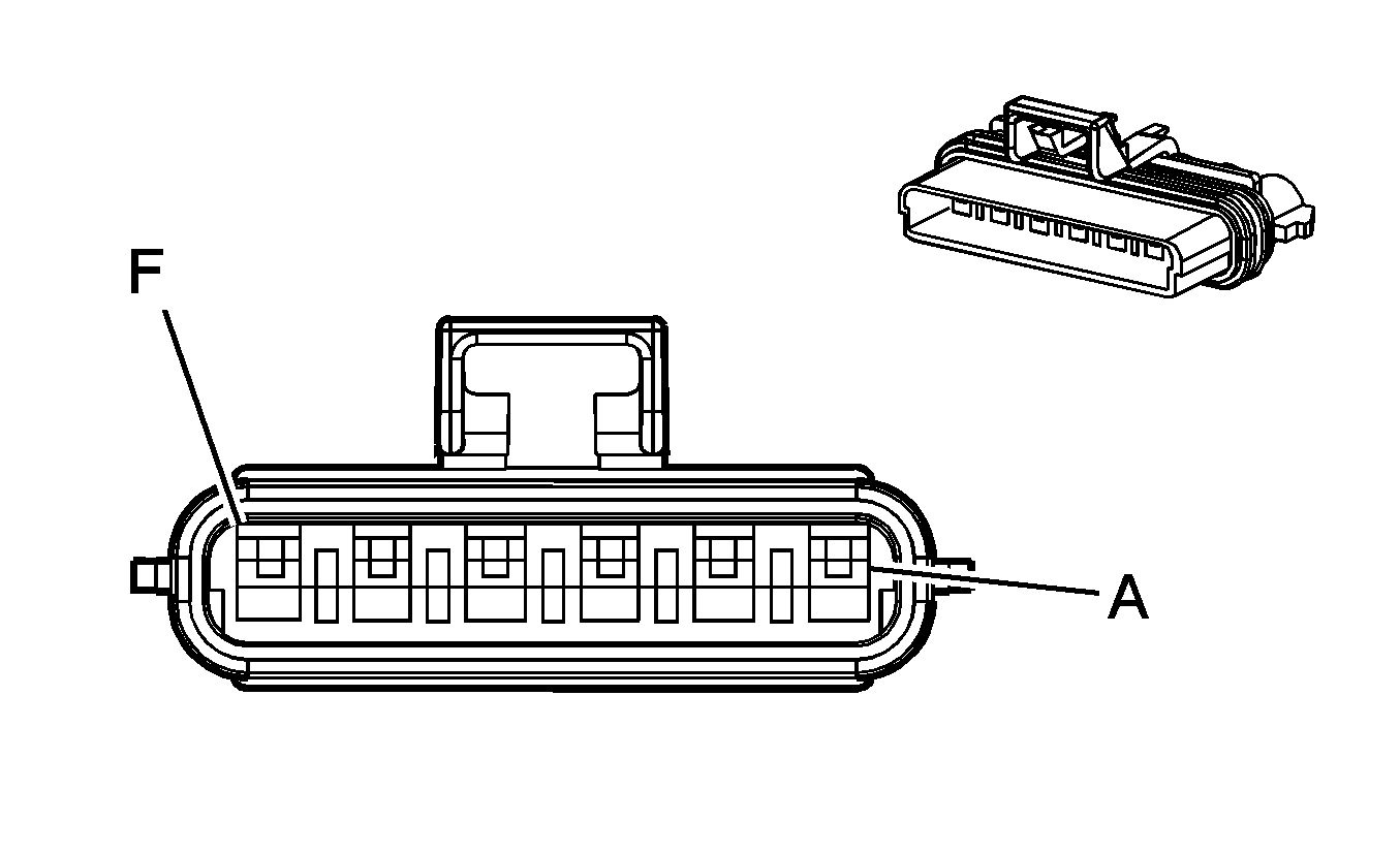
Pin | Wire Color | Circuit No. | Function | ||||
A | RED | 542 | Fuse Output Battery - Type II Fuse | ||||
B | ORN | 52 | Blower Switch Output (High) | ||||
C | BLK | 150 | Ground | ||||
D | TAN | 63 | Blower Switch Output (Medium 1) | ||||
E | YEL | 60 | Blower Switch Output (Low) | ||||
F | LT BLU | 72 | Blower Switch Output (Medium 2) | ||||
| |||||||
|---|---|---|---|---|---|---|---|
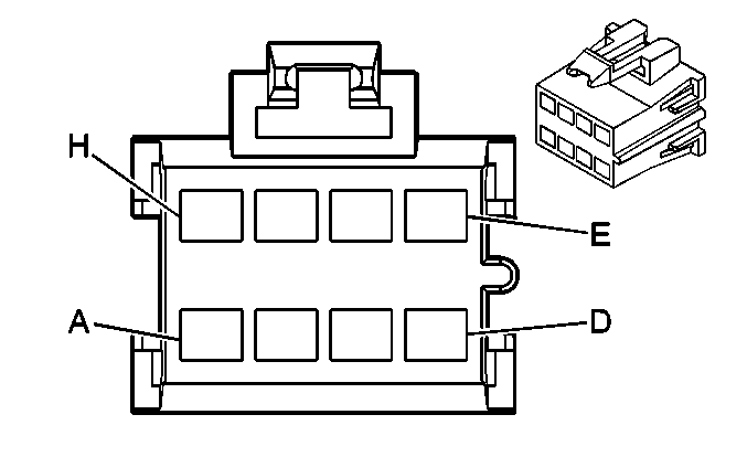
Connector Part Information |
| ||||||
Pin | Wire Color | Circuit No. | Function | ||||
A | GRY | 8 | Instrument Panel Lamp Supply Voltage - 1 | ||||
B | BLK | 150 | Ground | ||||
C | YEL | 60 | Low [position X] Blower Motor Control | ||||
D | ORN | 52 | High [position X] Blower [Motor] Control | ||||
E | TAN | 63 | Medium 1 [position X] Blower Motor Control | ||||
F | LT BLU | 203 | A/C Request Signal | ||||
G | BRN | 341 | Ignition 3 Voltage | ||||
H | DK GRN | 734 | Inside Air Temperature Sensor Signal | ||||
J | LT BLU | 733 | Air Temperature Door Position Signal | ||||
K | -- | -- | Not Used | ||||
| |||||||
|---|---|---|---|---|---|---|---|
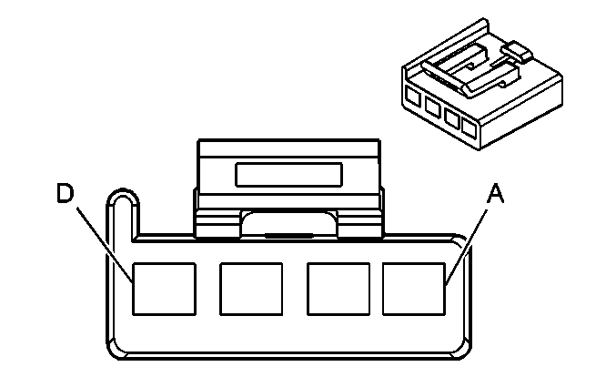
Connector Part Information |
| ||||||
Pin | Wire Color | Circuit No. | Function | ||||
A | YEL | 60 | Blower Switch Output (Low) | ||||
B | TAN | 63 | Blower Switch Output (Medium 1) | ||||
C | LT BLU | 72 | Blower Switch Output (Medium 2) | ||||
D | ORN | 52 | Blower Switch Output (High) | ||||
E | BRN | 141 | Fuse Output - IGN 3 - Type III Fuse | ||||
F | LT BLU | 733 | AIR Temperature Valve Position Sensor Signal | ||||
G | WHT | 119 | Mode Switch Output | ||||
H | LT GRN | 66 | AIR Conditioning Switch Output | ||||
| |||||||
|---|---|---|---|---|---|---|---|
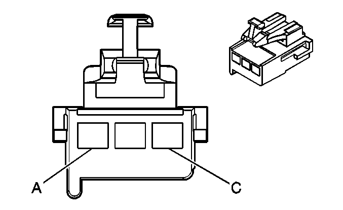
Connector Part Information |
| ||||||
Pin | Wire Color | Circuit No. | Function | ||||
A | ORN | 1440 | Fuse Output - Battery - Type III Fuse | ||||
B | BRN | 141 | Fuse Output - IGN 3 - Type III Fuse | ||||
C | BLK | 150 | Ground | ||||
D | ORN | 267 | Heated Mirror Element Feed | ||||
| |||||||
|---|---|---|---|---|---|---|---|
Connector Part Information |
| ||||||
Pin | Wire Color | Circuit No. | Function | ||||
A | WHT | 119 | Mode Switch Output | ||||
B | BLK | 150 | Ground | ||||
C | GRY | 8 | Instrument Panel Lamp Feed | ||||
| |||||||
|---|---|---|---|---|---|---|---|
Connector Part Information |
| ||||||
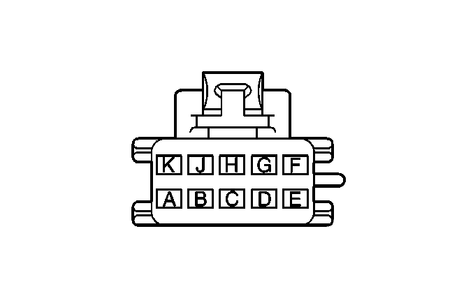
Pin | Wire Color | Circuit No. | Function | ||||
A | GRY | 8 | Instrument Panel Lamp Supply Voltage - 1 | ||||
B | BLK | 150 | Ground | ||||
C | YEL | 60 | Low [position X] Blower Motor Control | ||||
D | ORN | 52 | High [position X] Blower [Motor] Control | ||||
E | TAN | 63 | Medium 1 [position X] Blower Motor Control | ||||
F | DK BLU | 77 | Heater and A/C Control Logic Module - Signal | ||||
G | BRN | 341 | Ignition 3 Voltage | ||||
H | DK GRN | 734 | Inside Air Temperature Sensor Signal | ||||
J | LT BLU | 733 | Air Temperature Door Position Signal | ||||
K | -- | -- | Not Used | ||||
| |||||||
|---|---|---|---|---|---|---|---|
Connector Part Information |
| ||||||
Pin | Wire Color | Circuit No. | Function | ||||
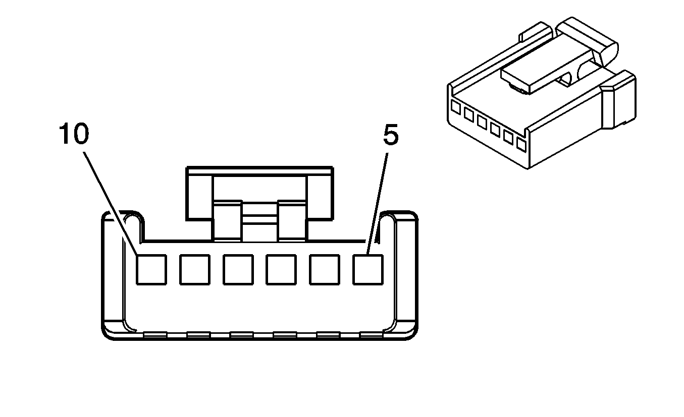
5 | -- | -- | Not Used | ||||
6 | -- | -- | Not Used | ||||
7 | BLK | 150 | Ground | ||||
8 | LT BLU | 773 | Air Temperature Valve Position Sensor - Signal | ||||
9 | -- | -- | Not Used | ||||
10 | BRN | 341 | Ignition 3 Voltage I | ||||

| |||||||
|---|---|---|---|---|---|---|---|
Connector Part Information |
| ||||||
Pin | Wire Color | Circuit No. | Function | ||||
5-6 | -- | -- | Not Used | ||||
7 | BLK | 150 | Ground | ||||
8 | DK GRN | 734 | Inside Air Temperature Sensor Signal | ||||
9 | -- | -- | Not Used | ||||
10 | BRN | 341 | Ignition 3 Voltage | ||||
