Engine Oil Pressure Sensor or Switch Replacement 4.3L
Tools Required
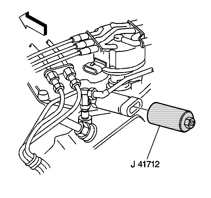
J 41712 Oil Pressure Switch Socket
Removal Procedure
- Remove the engine cover. Refer to Engine Cover Replacement in Interior Trim.
- Disconnect the engine oil pressure (EOP) gauge sensor electrical connector.
- Hold the engine EOP gauge sensor fitting with a wrench.
- Remove the engine EOP gauge sensor using J 41712 .
- Remove the EOP gauge sensor fitting, if necessary.
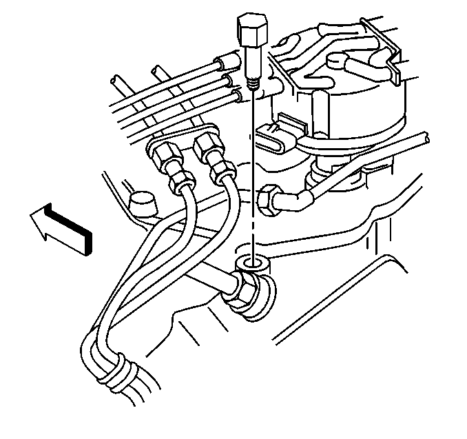
Important: Note the alignment of the EOP gauge sensor fitting prior to removal.
Installation Procedure
- Install the EOP gauge sensor fitting, if removed.
- Tighten the sensor fitting until properly aligned.
- Install the EOP gauge sensor.
- Hold the EOP gauge sensor fitting with a wrench to prevent from turning. Use the J 41712 in order to tighten the EOP gauge sensor.
- Connect the EOP gauge sensor electrical connector.
- Install the engine cover. Refer to Engine Cover Replacement in Interior Trim.

Notice: Replacement components must be the correct part number for the application. Components requiring the use of the thread locking compound, lubricants, corrosion inhibitors, or sealants are identified in the service procedure. Some replacement components may come with these coatings already applied. Do not use these coatings on components unless specified. These coatings can affect the final torque, which may affect the operation of the component. Use the correct torque specification when installing components in order to avoid damage.
Tighten
Tighten the fitting to 15 N·m (11 lb ft).
Important: Do not loosen the sensor fitting. Do not tighten the sensor fitting more than one turn to align.

Tighten
Tighten the sensor to 30 N·m (22 lb ft).
Engine Oil Pressure Sensor or Switch Replacement 5.7L
Tools Required
J 41712 Oil Pressure Switch Socket
Removal Procedure
- Remove the engine cover. Refer to Engine Cover Replacement in Interior Trim.
- Remove the air cleaner assembly. Refer to Air Cleaner Assembly Replacement in Engine Controls - 5.7L.
- Disconnect the electrical connector from the engine oil pressure (EOP) gauge sensor.
- Hold the EOP gauge sensor fitting with a wrench.
- Remove the EOP gauge sensor using J 41712 .
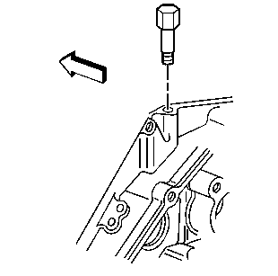
- Remove the EOP sensor fitting, if necessary.

Important: Note the alignment of the EOP gauge sensor fitting prior to removal.
Installation Procedure
- Apply sealant GM P/N 12346004 or equivalent to the threads of the EOP sensor fitting.
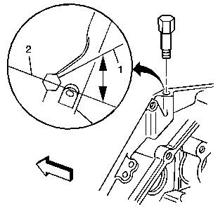
- Install the EOP gauge sensor fitting.
- Rotate the EOP sensor fitting clockwise to the proper position (1), 50 degrees from the centerline (2).
- Install the EOP sensor.
- Hold the EOP sensor fitting with a wrench to prevent from turning. Use the J 41712 in order to tighten the EOP sensor.
- Connect the electrical connector.
- Install the engine cover. Refer to Engine Cover Replacement in Interior Trim.
- Install the air cleaner assembly. Refer to Air Cleaner Assembly Replacement in Engine Controls - 5.7L.
Important: Do not loosen the EOP sensor fitting after the initial torque has been obtained.
Notice: Replacement components must be the correct part number for the application. Components requiring the use of the thread locking compound, lubricants, corrosion inhibitors, or sealants are identified in the service procedure. Some replacement components may come with these coatings already applied. Do not use these coatings on components unless specified. These coatings can affect the final torque, which may affect the operation of the component. Use the correct torque specification when installing components in order to avoid damage.
Tighten
Tighten the fitting to 15 N·m (11 lb ft).
Important: Do not rotate the EOP sensor fitting more than 359 degrees after the initial torque has been obtained.

Tighten
Tighten the sensor to 30 N·m (22 lb ft).
Engine Oil Pressure Sensor or Switch Replacement 6.5L
Tools Required
J 41712 Oil Pressure Switch Socket
Removal Procedure
- Remove the engine cover from the vehicle. Refer to Engine Cover Replacement in Interior Trim.
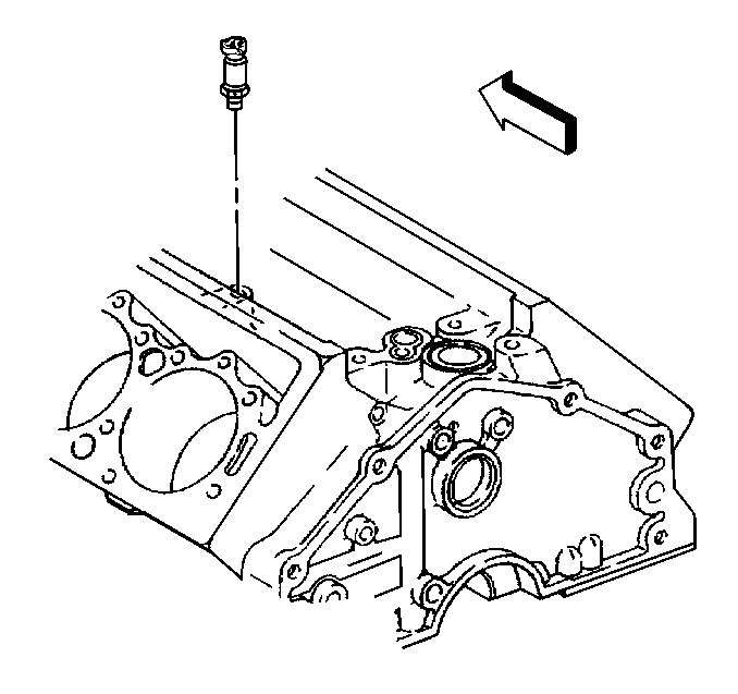
- Remove the electrical connector from the engine oil pressure (EOP) sending unit.
- Use the J 41712 in order to remove the EOP sending unit from the engine block.
Installation Procedure
- Use the J 41712 in order to install the EOP sending unit to the engine block.
- Connect the electrical connector to the EOP sending unit.
- Install the engine cover in the vehicle. Refer to Engine Cover Replacement in Interior Trim.

Notice: Replacement components must be the correct part number for the application. Components requiring the use of the thread locking compound, lubricants, corrosion inhibitors, or sealants are identified in the service procedure. Some replacement components may come with these coatings already applied. Do not use these coatings on components unless specified. These coatings can affect the final torque, which may affect the operation of the component. Use the correct torque specification when installing components in order to avoid damage.
Tighten
Tighten the oil sending unit to 12 N·m (9 lb ft).
Engine Oil Pressure Sensor or Switch Replacement 8.1L
Tools Required
J 25254-10 A Oil Pressure Sending Unit Socket
Removal Procedure
- Remove the engine cover. Refer to Engine Cover Replacement in Interior Trim.
- Disconnect the electrical connector.
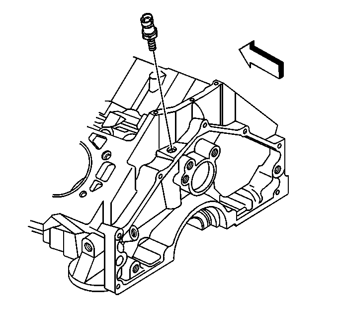
- Remove the engine oil pressure (EOP) sensor using J 25254-10 A .
Installation Procedure
- Install the EOP sensor.
- Hold the EOP sensor fitting with a wrench to prevent from turning. Use J 25254-10 A in order to tighten the EOP sensor.
- Connect the electrical connector.
- Install the engine cover. Refer to Engine Cover Replacement in Interior Trim.

Notice: Replacement components must be the correct part number for the application. Components requiring the use of the thread locking compound, lubricants, corrosion inhibitors, or sealants are identified in the service procedure. Some replacement components may come with these coatings already applied. Do not use these coatings on components unless specified. These coatings can affect the final torque, which may affect the operation of the component. Use the correct torque specification when installing components in order to avoid damage.
Tighten
Tighten the sensor to 30 N·m (22 lb ft).
