Tools Required
J 7872 Magnetic Base Dial Indicator
Removal Procedure
- Remove the engine front cover. Refer to Engine Front Cover Replacement .
- Attach the J 7872 to the front of the engine cylinder block.
- Using finger pressure on the inside radius of the timing chain, push the timing chain outward (parallel to the front face of the block) to the maximum deflection.
- Set the J 7872 to zero.
- Using finger pressure on the outside radius of the timing chain, push the timing chain inward (parallel to the front face of the block) to the maximum deflection.
- Note the deflection of the timing chain (total travel of the magnetic base dial indicator plunger).
- If the deflection exceeds the limit, replace the worn parts.
- Remove the bolt from the timing chain sprocket to the camshaft.
- Remove the fuel injection pump drive gear from the timing chain sprocket.
- Remove the timing chain and sprocket from the camshaft.
- Remove the sprocket from the crankshaft.
- Inspect the timing chain sprocket key.
- Inspect the crankshaft gear key for damage.
- Replace the keys if damage is found.
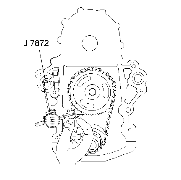
| • | Position the magnetic base dial indicator to allow the plunger to contact the timing chain. |
| • | The magnetic base dial indicator plunger should contact the timing chain centered between the two sprockets. |
| • | For used parts, the deflection must not exceed 20.3 mm (0.80 in). |
| • | For new parts, the deflection must not exceed 12.7 mm (0.50 in). |
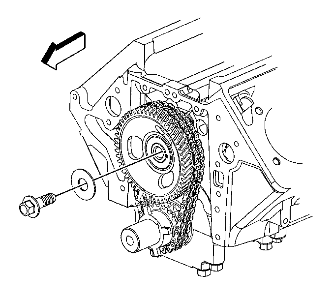
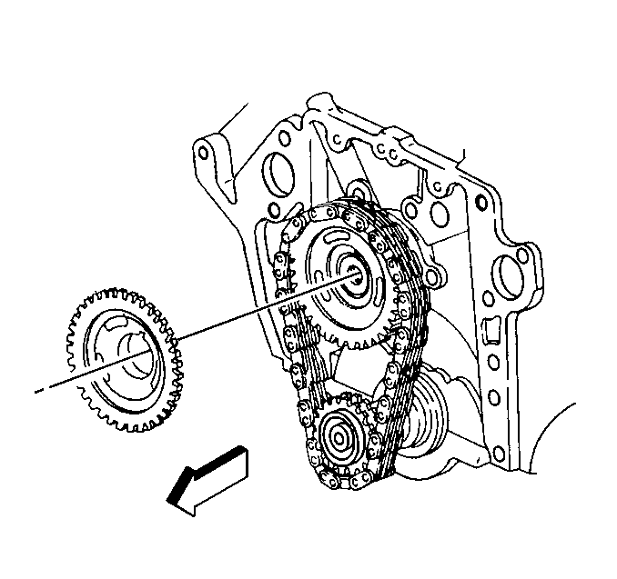
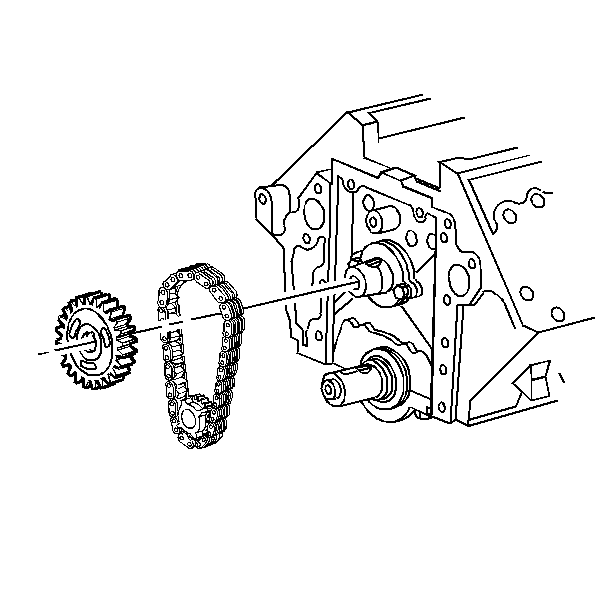
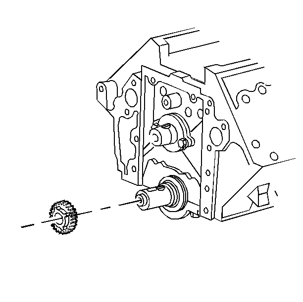
Important: Replace the timing chain sprocket key if there are signs of excessive wear or damage. Do not try to repair the key.
Installation Procedure
- Install the key in the crankshaft, if removed.
- Install the key in the camshaft, if removed.
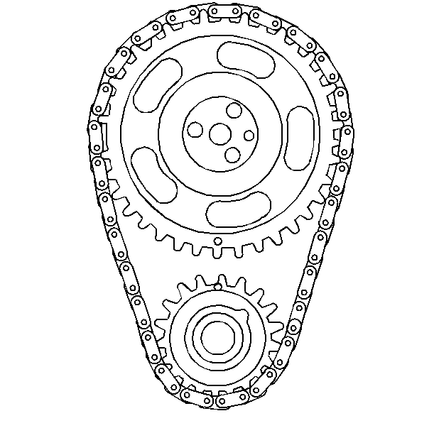
- Install the crankshaft sprocket with the reluctor wheel square bosses facing the front to the crankshaft.
- Align the timing marks.
- Install the camshaft sprocket with the timing chain.
- Install the timing chain sprocket bolt to the camshaft.
- Perform steps 2 through 6 of the removal procedure to measure the timing chain deflection.
- Install the engine front cover to the engine block. Refer to Engine Front Cover Replacement .
- Perform TDC offset timing adjustment. Refer to Fuel Injection Pump Top Dead Center Offset Adjustment in Engine Controls-6.5L (L65).

Important: Do not damage the reluctor wheel square bosses.


Notice: Use the correct fastener in the correct location. Replacement fasteners must be the correct part number for that application. Fasteners requiring replacement or fasteners requiring the use of thread locking compound or sealant are identified in the service procedure. Do not use paints, lubricants, or corrosion inhibitors on fasteners or fastener joint surfaces unless specified. These coatings affect fastener torque and joint clamping force and may damage the fastener. Use the correct tightening sequence and specifications when installing fasteners in order to avoid damage to parts and systems.
Tighten
Tighten the bolt to 170 N·m (125 lb ft).
Notice: Perform TDC Offset Recovery procedure if the timing chain, timing gears, engine front cover, crankshaft position sensor, crankshaft or other components affecting the timing are replaced.
