For 1990-2009 cars only
Removal Procedure
Important: As originally installed, the upper control arm cannot be adjusted for caster or camber. If the caster and camber is out of specifications, the caster and camber can be set to the right specifications.
- Raise the vehicle. Refer to Lifting and Jacking the Vehicle in General Information.
- Remove the tire and the wheel from the vehicle. Refer to Tire and Wheel Removal and Installation in Tires and Wheels.
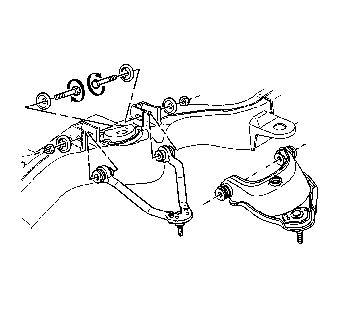
- Remove the upper control arm from the frame bracket. Refer to Upper Control Arm Replacement in Front Suspension.
- Remove any wax coatings in the knockout area in order to make the stamped outline visible for removing.
- Use a suitable cutting tool to remove the frame bracket knockout from the frame of the vehicle.
- Repeat the same procedure for the other upper control arm frame bracket knockout.

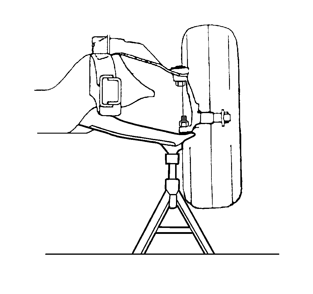
Important: Place safety stands under the lower control arms during the removal and the installation in order to retain the lower control arm position.

Do not distort the frame bracket when removing the knockout.
Installation Procedure
- Install the upper control arm into the frame brackets. Refer to Upper Control Arm Replacement in Front Suspension.
- Install the bolts , cams and washers to the control arm. Partially tighten the nuts in order to align the vehicle.
- Install the tire and the wheel. Refer to Tire and Wheel Removal and Installation in Tires and Wheels.
- Remove the safety stands.
- Lower the vehicle.
- Align the vehicle. Refer to Front Caster and Camber Adjustment or Front Toe Adjustment .

