For 1990-2009 cars only
Tools Required
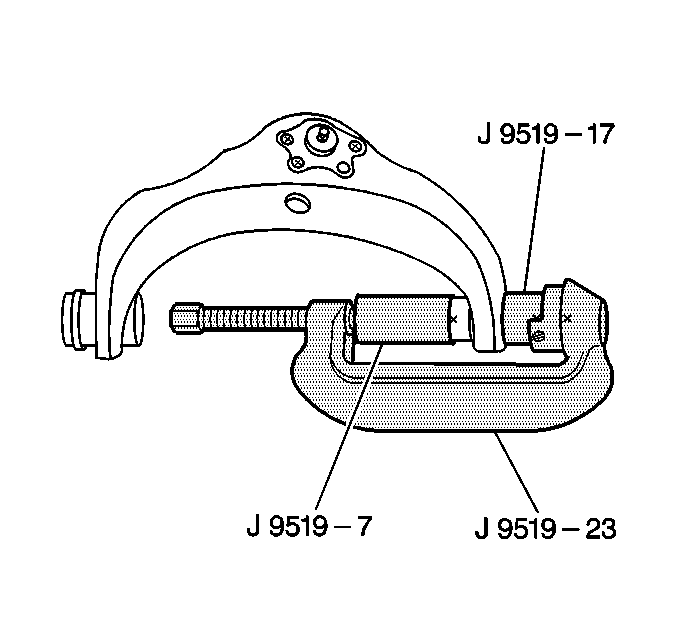
J 9519-E Ball Joint Remover/Installer Set
Removal Procedure
- Raise the vehicle.
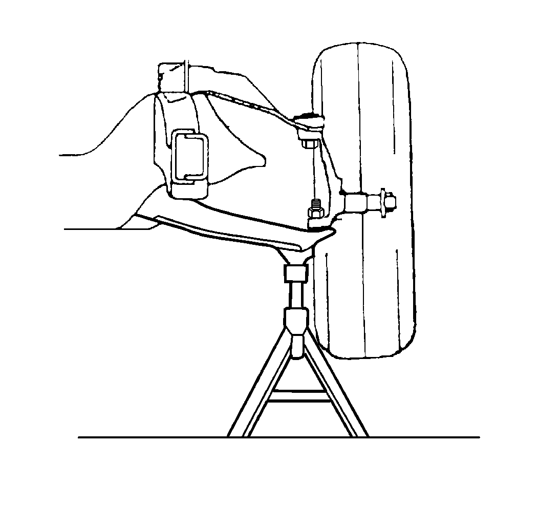
- Support the vehicle with suitable safety stands.
- Support the lower control arm with safety stands.
- Remove the tire and wheel assembly. Refer to Tire and Wheel Removal and Installation in Tires and Wheels.
- Remove the upper control arm from the vehicle. Refer to Upper Control Arm Replacement .
- Using the J 9519-17 as shown remove the upper control arm bushings from the control arm.
Caution: To avoid any vehicle damage, serious personal injury or death when major components are removed from the vehicle and the vehicle is supported by a hoist, support the vehicle with jack stands at the opposite end from which the components are being removed and strap the vehicle to the hoist.
Caution: Floor jack must remain under the lower control arm during removal and installation to retain the lower control arm in position. Failure to do so could result in personal injury.


Remove the tool.
Installation Procedure
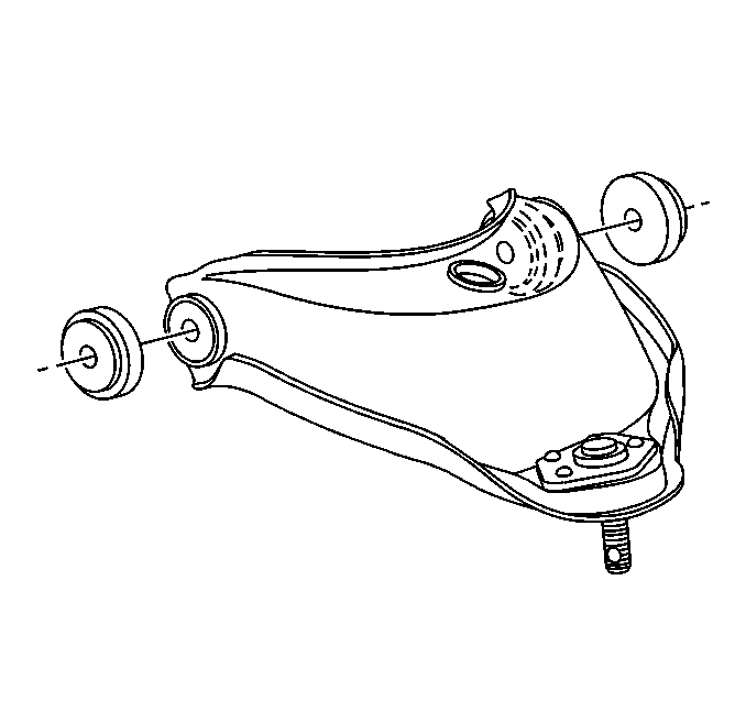
- Insert the new control arm bushings into the control arm.
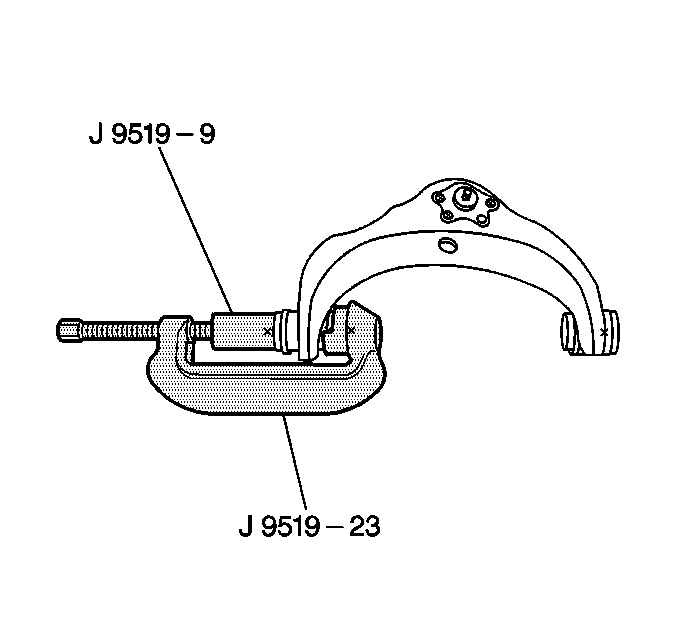
- Using the J 9519-23 as shown install the upper control arm bushings into the control arm.
- Remove the tool.
- Install the upper control arm to the vehicle. Refer to Upper Control Arm Replacement .
- Install the tire and wheel assembly. Refer to Tire and Wheel Removal and Installation in Tires and Wheels.
- Remove the safety stands.
- Lower the vehicle.
- Check the wheel alignment. Refer to Wheel Alignment Specifications in Wheel Alignment.


Important: Make sure the bushings are properly seated in the control arm.
