Tools Required
| • | J 42137 Lock
Plate Compressor Adapter |

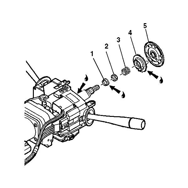
- Lubricate the following
parts with synthetic grease:
| • | The lower brass surface of the turn signal cancel cam assembly (4) |
- Install the following parts onto the steering shaft assembly:
| 2.2. | The upper bearing inner race seat (2) |
| 2.3. | The upper bearing spring (3) |
| 2.4. | The turn signal cancel cam assembly (4) |
| 2.5. | The shaft lock shield assembly (5) |

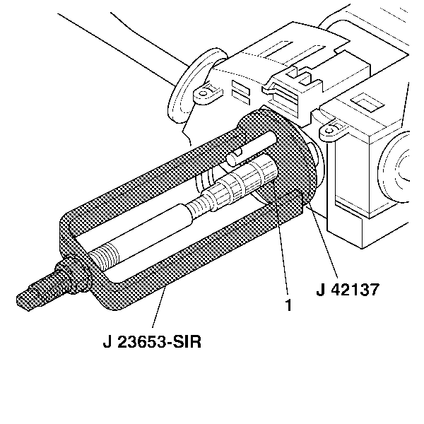
- Compress the shaft lock
shield assembly (2) using J 23653-SIR
and J 42137
.
- Install the new bearing retainer (1) onto the steering
shaft assembly.
- Firmly seat the bearing retainer (1) into the groove on
the steering shaft assembly.
- Remove J 23653-SIR
and J 42137
from
the steering shaft assembly.
Caution: Improper routing of the wire harness assembly may damage the inflatable
restraint steering wheel module coil. This may result in a malfunction of
the coil, which may cause personal injury.
- Install the inflatable restraint steering wheel module
coil. Refer to
Inflatable Restraint Steering Wheel Module Coil Assemble - Off Vehicle
.
- Enable the inflatable restraint steering wheel module. Refer to
Enabling the SIR System
in SIR.


