Removal Procedure
- Disconnect the battery negative cable from the battery. Refer to Battery Negative Cable Disconnection and Connection in Engine Electrical.
- Remove the engine cover from the vehicle. Refer to Engine Cover Replacement in Interior Trim.
- Remove the air cleaner assembly from the vehicle. Refer to Air Cleaner Assembly Replacement in Engine Controls-6.5L (L65).
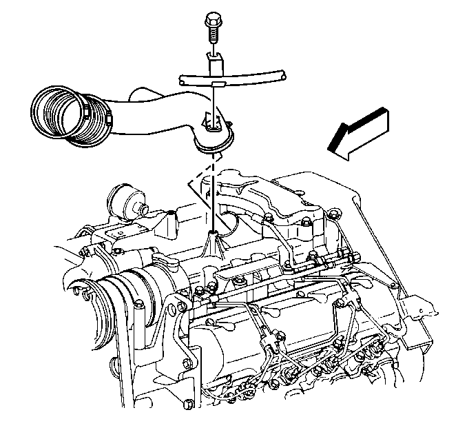
- Remove the air intake duct from the turbocharger.
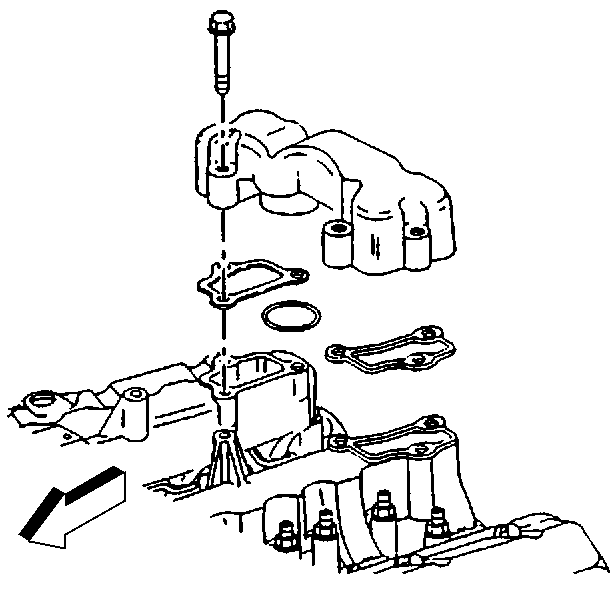
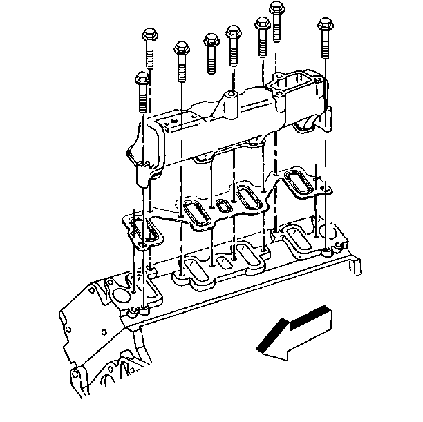
- Remove the upper intake manifold bolts.
- Remove the upper intake manifold.
- Remove the gaskets from the lower intake manifold.
- Remove the seal from the turbocharger.
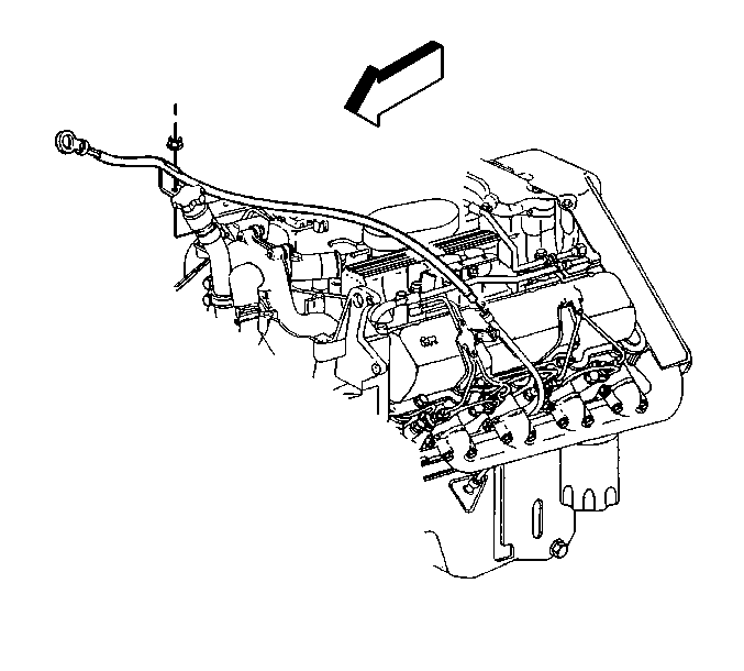
- Remove the transmission oil level indicator tube upper section from the upper intake manifold.
- Remove the oil level indicator from the tube.
- Remove the nut retaining the oil level indicator to the thermostat crossover.
- Separate the upper section of the oil level indicator tube from the lower section.
- If equipped with rear air conditioning (A/C), remove the rear A/C pipe from the A/C compressor. Refer to Compressor Hose Assembly Replacement in Heating, Ventilation and Air Conditioning.
- Remove the nuts retaining the rear A/C pipe brackets from the upper intake manifold (if equipped).
- Position the rear A/C pipe our of the way.
- Drain the engine coolant. Refer to Cooling System Draining and Filling in Engine Cooling.
- Remove the upper radiator hose.
- Disconnect the gray engine harness electrical connector.
- Remove the electrical harness and retaining brackets from the upper intake manifold (if needed).
- Remove the nuts retaining the fuel pipe brackets.
- Remove the bracket for retaining the CDR valve from the right side lower intake manifold studs.
- Remove the CDR valve.
- Disconnect the intake air temperature (IAT) sensor electrical connector.
- Remove the IAT sensor.
- Disconnect the Boost sensor electrical connector by releasing the locking tab.
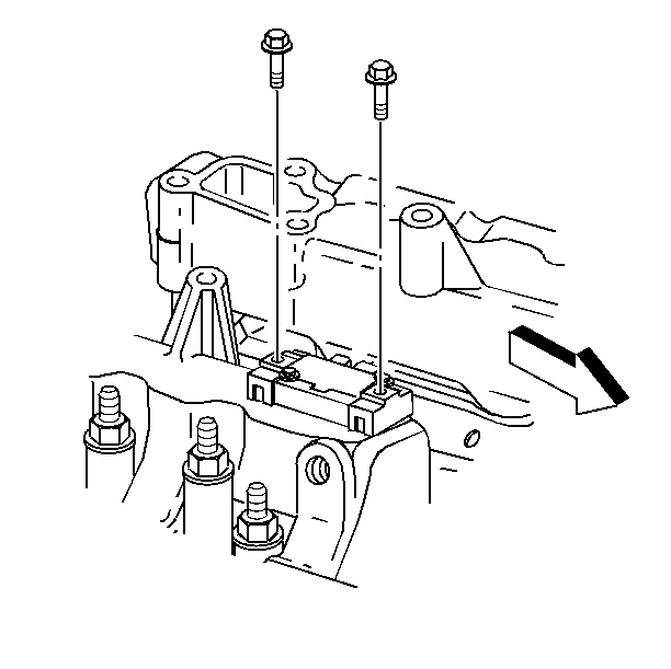
- Remove the Boost sensor retaining bolts.
- Remove the Boost sensor.
- Remove the gasket.
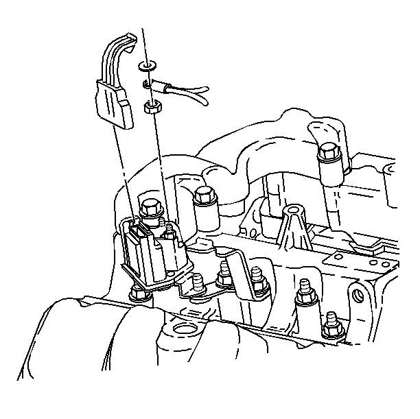
- Disconnect the glow plug relay electrical connectors by releasing the locking tab.
- Remove the hold down nuts on the glow plug relay power supply terminals.
- Remove the glow plug relay power supply terminals.
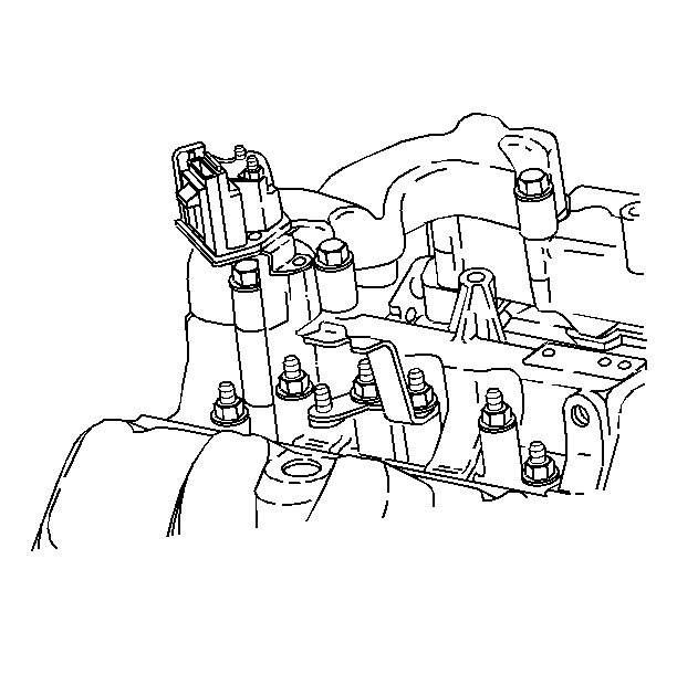
- Remove the glow plug relay retaining nuts.
- Remove the glow plug relay.
- Disconnect the wastegate solenoid wiring harness connector by releasing the locking tab.
- Remove the vacuum hose harness.
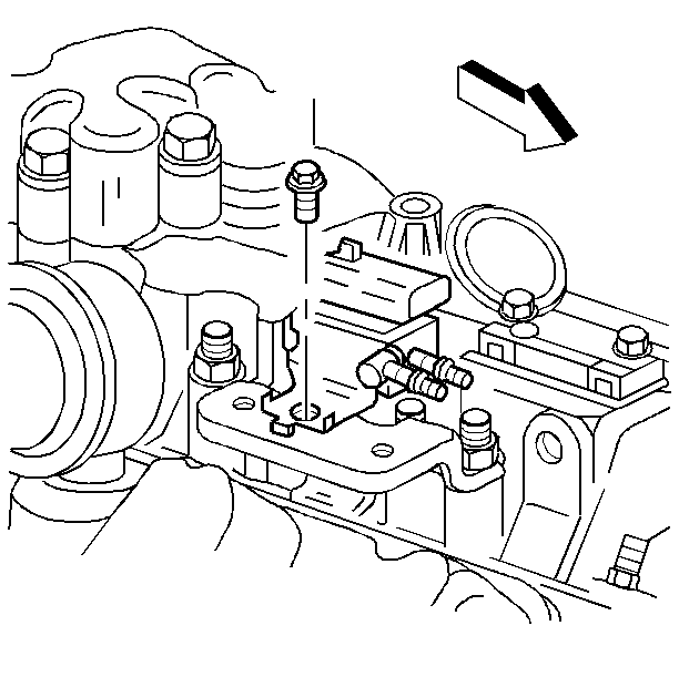
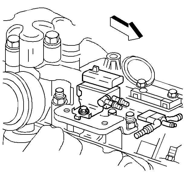
- Remove the wastegate solenoid retaining bolts.
- Remove the wastegate solenoid.
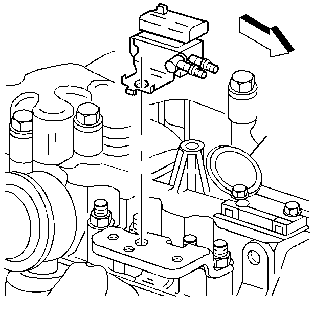
- Remove the wastegate solenoid mounting bracket retaining nuts.
- Remove the wastegate solenoid mounting bracket.
- Remove the electrical harness retaining clips.
- Position the engine wiring harness out of the way.
- Remove the lower intake manifold bolts.
- Remove the lower intake manifold and gaskets from the cylinder heads.
- Inspect and clean the sealing surfaces.
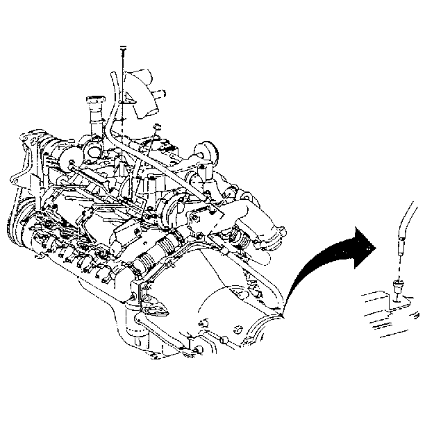
Important: The lower intake comes in two sections. If replacing both the left side and the right side perform all of the following steps. If replacing only the left side perform steps 9 to 22 and step 42 to 44. If replacing only the right side perform steps 22 to 44.
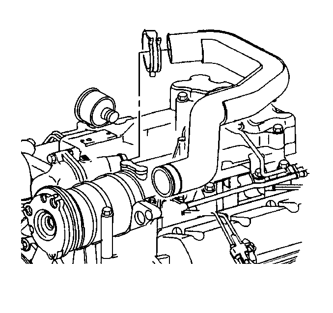
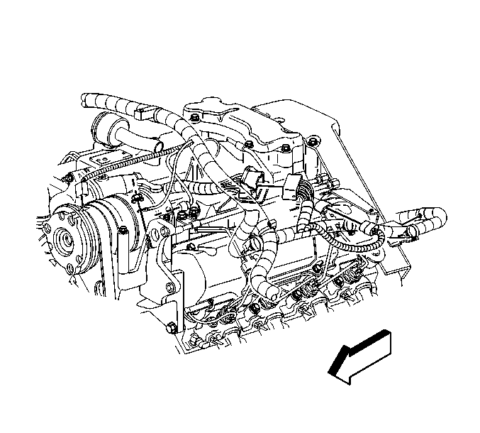
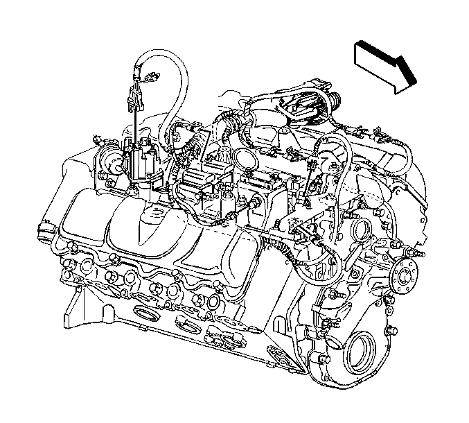
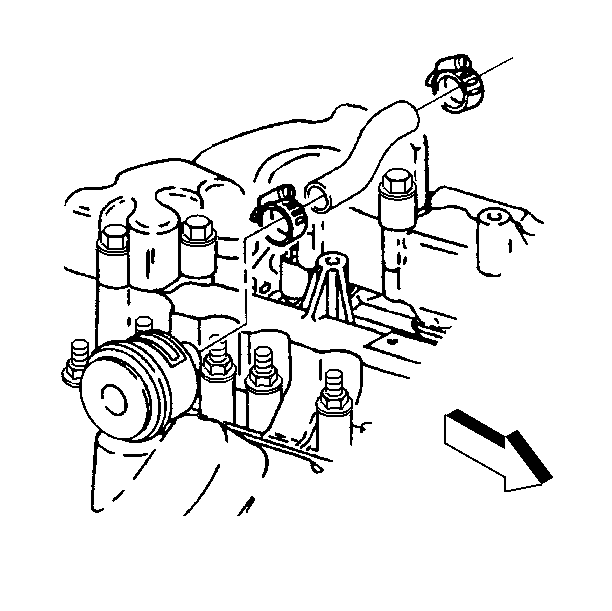
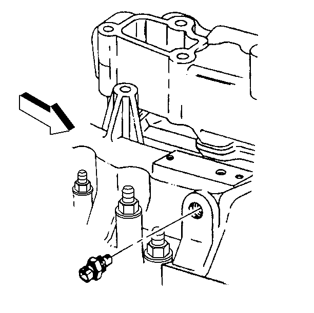
Important: The sensors and the solenoids attached to the lower intake manifold require removal in order to prevent damage when cleaning with solvent cleaning.

Installation Procedure
- Install the new gaskets onto the cylinder heads.
- Install the intake manifolds.
- Apply teflon sealer GM P/N 1236004 on the threads of the studs that are second to the end on both intake manifolds. There are a total of four studs that require the teflon sealer.
- Apply threadlocker GM P/N 12345382 on the threads of the remaining studs.
- Install the intake manifold studs.
- Install the miscellaneous brackets and fuel line brackets on the intake studs.
- Install the nuts for the brackets.
- Position the engine wiring harness.
- Install the electrical harness in the retaining clips.
- Install the wastegate solenoid mounting bracket.
- Install the wastegate solenoid mounting bracket retaining nuts.
- Instal the wastegate solenoid.
- Instal the wastegate solenoid retaining bolts.
- Connect the wastegate solenoid wiring harness connector.
- Install the vacuum hose harness.
- Install the glow plug relay.
- Install the glow plug relay retaining nuts.
- Install the glow plug relay power supply terminals.
- Install the hold down nuts on the glow plug relay power supply terminals.
- Connect the glow plug relay electrical connector.
- Install the Boost sensor gasket.
- Install the Boost sensor.
- Install the Boost sensor retaining bolts.
- Connect the Boost sensor electrical connector.
- Install the IAT sensor.
- Connect the intake air temperature (IAT) sensor electrical connector.
- Install the CDR valve.
- Install the bracket for retaining the CDR valve to the right side lower intake manifold studs.
- Instal the electrical harness and retaining brackets and nuts.
- Install the nuts retaining the fuel pipe brackets.
- Connect the gray engine harness electrical connector.
- Install the upper radiator hose.
- If equipped with rear air conditioning (A/C), install the rear A/C pipe to the A/C compressor. Refer to Compressor Hose Assembly Replacement in Heating, Ventilation and Air Conditioning.
- Install new upper intake manifold gaskets to the lower intake manifolds.
- Install a new O-ring onto the turbocharger inlet housing.
- Lightly lubricate the O-ring with clean engine oil.
- Install the upper intake manifold to the lower intake manifolds.
- Install the upper intake manifold bolts
- Install a small amount of RTV sealant GM P/N 12346286 to the area on the upper tube where it joins with the lower tube.
- Install the upper oil level indicator tube.
- Install the nut retaining the oil level indicator tube to the thermostat cross over.
- Install the oil level indicator.
- For the 6.5L diesel engine, install the bolt and the nut securing the oil level indicator tube brackets to the engine.
- Fill the engine coolant. Refer to Cooling System Draining and Filling in Engine Cooling.
- Recharge the A/C system, if required. Refer to Refrigerant Recovery and Recharging in Heating, Ventilation, and Air Conditioning.
- Install the air intake duct from the turbocharger.
- Connect the battery negative cable from the battery. Refer to Battery Negative Cable Disconnection and Connection in Engine Electrical.
- Install the air cleaner assembly from the vehicle. Refer to Air Cleaner Assembly Replacement in Engine Controls-6.5L (L65).
- Install the engine cover from the vehicle. Refer to Engine Cover Replacement in Interior Trim.

Notice: Use the correct fastener in the correct location. Replacement fasteners must be the correct part number for that application. Fasteners requiring replacement or fasteners requiring the use of thread locking compound or sealant are identified in the service procedure. Do not use paints, lubricants, or corrosion inhibitors on fasteners or fastener joint surfaces unless specified. These coatings affect fastener torque and joint clamping force and may damage the fastener. Use the correct tightening sequence and specifications when installing fasteners in order to avoid damage to parts and systems.
Tighten
Tighten the intake manifold studs, (from the center out) to 42 N·m
(31 lb ft).
Tighten
Tighten the bracket nuts to 23 N·m (17 lb ft).


Tighten
Tighten the bracket nuts to 23 N·m (17 lb ft).
Tighten
Tighten the wastegate solenoid bolts to 3.5 N·m (27 lb in).


Tighten
Tighten the bracket nuts to 42 N·m (37 lb ft).

Tighten
Tighten the terminal nuts to 4 N·m (44 lb in).

Tighten
Tighten the terminal nuts to 3.5 N·m (27 lb in).

Tighten
Tighten the IAC sensor to 25 N·m (18 lb ft).

Tighten
Tighten the bracket nuts to 23 N·m (17 lb ft).

Tighten
Tighten the bracket nuts to 23 N·m (17 lb ft).


Important: Always replace the O-ring between the upper intake manifold and the turbocharger.
Tighten
Tighten the upper intake manifold bolts to 23 N·m (17 lb ft).

Tighten
Tighten the oil level indicator tube nut to 22 N·m (16 lb ft).
Tighten
| • | Tighten the bolt to 47 N·m (35 lb ft). |
| • | Tighten the nut to 25 N·m (18 lb ft). |

