Leaf Spring Replacement Passenger/Cargo
Removal Procedure
- Raise the vehicle on a hoist.
- Support the rear axle in order to relieve the tension from the rear springs, using a suitable jack stand.
- Remove the tire and wheel assembly. Refer to Tire and Wheel Removal and Installation in Tires and Wheels.
- Remove the following parts from the axle:
- Lower the jack stand slightly in order to remove the axle from the rear spring.
- Lower the axle in order to remove the locator pin on the rear spring from the axle.
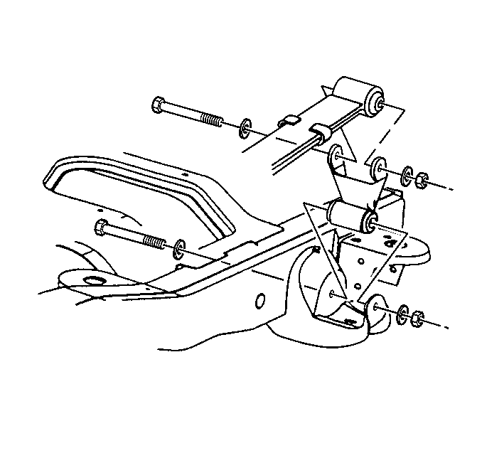
- Remove the rear of the rear spring from the rear of the rear spring shackle.
- Remove the rear spring from the front frame hanger.
- Remove the nut and the bolt that retain the rear shackle to the rear spring.
- Remove the rear spring from the vehicle.
- Insert the spring into a suitable holding fixture.
- Remove the rear shackle.

Caution: To avoid any vehicle damage, serious personal injury or death when major components are removed from the vehicle and the vehicle is supported by a hoist, support the vehicle with jack stands at the opposite end from which the components are being removed and strap the vehicle to the hoist.
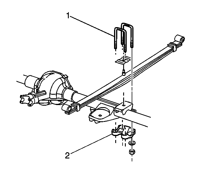
| • | The rear spring U-bolts (1) |
| • | The anchor plate (2) |

Installation Procedure
- Install the rear shackle to the rear spring.
- Install the nut and the bolt to the shackle.
- Install the rear spring to the vehicle.
- Install the rear spring to the front frame hanger.
- Install the rear spring shackle to the rear frame hanger.
- Install the following parts that are connected to the axle:
- Install the tire and wheel. Refer to Tire and Wheel Removal and Installation in Tires and Wheels.
- Remove the axle support.

Notice: Use the correct fastener in the correct location. Replacement fasteners must be the correct part number for that application. Fasteners requiring replacement or fasteners requiring the use of thread locking compound or sealant are identified in the service procedure. Do not use paints, lubricants, or corrosion inhibitors on fasteners or fastener joint surfaces unless specified. These coatings affect fastener torque and joint clamping force and may damage the fastener. Use the correct tightening sequence and specifications when installing fasteners in order to avoid damage to parts and systems.
Important: Use a new bolt and a new nut each time the service is performed.
Tighten
Tighten the rear spring to the front hanger nut to 110 N·m (80 lb ft)
+ a 200 degree turn.
Important: Use a new bolt and a new nut each time the service is performed.
Tighten
Tighten the rear shackle to the rear frame hanger and the rear spring to 90 N·m
(67 lb ft).

Important: Tighten the outer U-bolt nuts and then tighten the inner U-bolt nuts to 25 N·m (18 lb ft). Then tighten the U-bolt nuts in a cross pattern sequence.
| • | The rear spring U-bolts (1) |
| • | The anchor plates (2) |
Tighten
| • | For vehicles below 7300 GVW, tighten the U-bolt nuts to 95 N·m (70 lb ft). |
| • | For vehicles above 7300 GVW, tighten the U-bolt nuts to 150 N·m (115 lb ft). |
Lower the vehicle.
Leaf Spring Replacement Cutaway/Upfitter
Removal Procedure
- Raise the vehicle on a hoist.
- Support the rear axle in order to relieve the tension from the rear springs, using a suitable jack stand.
- Remove the tire and wheel assembly. Refer to Tire and Wheel Removal and Installation in Tires and Wheels.
- Remove the following parts from the axle:
- Lower the jack stand slightly in order to remove the axle from the rear spring.
- Lower the axle in order to remove the locator pin on the rear spring from the axle.
- Remove the rear of the rear spring from the rear of the rear spring shackle.
- Remove the rear spring from the front frame hanger.
- Remove the nut and the bolt that retain the rear shackle to the rear spring.
- Remove the rear spring from the vehicle.
- Insert the spring into a suitable holding fixture.
- Remove the rear shackle.

Caution: To avoid any vehicle damage, serious personal injury or death when major components are removed from the vehicle and the vehicle is supported by a hoist, support the vehicle with jack stands at the opposite end from which the components are being removed and strap the vehicle to the hoist.
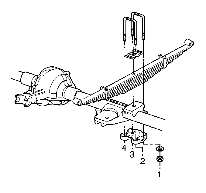
| • | The rear spring U-bolts |
| • | The anchor plate (2) |

Installation Procedure
- Install the rear shackle to the rear spring.
- Install the nut and the bolt to the shackle.
- Install the rear spring to the vehicle.
- Install the rear spring to the front frame hanger.
- Install the rear spring shackle to the rear frame hanger.
- Install the following parts that are connected to the axle:
- Install the tire and wheel. Refer to Tire and Wheel Removal and Installation in Tires and Wheels.
- Remove the axle support.

Important: Use a new bolt and a new nut each time the service is performed.
Notice: Use the correct fastener in the correct location. Replacement fasteners must be the correct part number for that application. Fasteners requiring replacement or fasteners requiring the use of thread locking compound or sealant are identified in the service procedure. Do not use paints, lubricants, or corrosion inhibitors on fasteners or fastener joint surfaces unless specified. These coatings affect fastener torque and joint clamping force and may damage the fastener. Use the correct tightening sequence and specifications when installing fasteners in order to avoid damage to parts and systems.
Tighten
Tighten the rear spring to the front hanger nut to 110 N·m (80 lb ft)
+ a 200 degree turn.
Important: Use a new bolt and a new nut each time the service is performed.
Tighten
Tighten the rear shackle to the rear frame hanger and the rear spring to 90 N·m
(67 lb ft).

Important: Tighten the outer U-bolt nuts and then tighten the inner U-bolt nuts (1) to 25 N·m (18 lb ft). Then tighten the U-bolt nuts (1) in a cross pattern sequence as shown.
| • | The rear spring U-bolts |
Tighten
| • | For vehicles below 7300 GVW, tighten the U-bolt nuts to 95 N·m (70 lb ft). |
| • | For vehicles above 7300 GVW, tighten the U-bolt nuts to 150 N·m (115 lb ft). |
| • | The anchor plates |
Lower the vehicle.
