Intake Manifold Installation G
Intake Manifold
- Install the new gaskets onto the cylinder heads.
- Install the intake manifolds.
- Apply teflon sealer GM P/N United States 12346004, GM P/N Canada 10953480, on the threads of the studs that are second to the end on both intake manifolds. There are a total of four studs that require the teflon sealer.
- Apply threadlocker GM P/N United States 12345493, GM P/N Canada 10953488, on the threads of the remaining studs.
- Install the intake manifold studs.
- Install the miscellaneous brackets and fuel line brackets on the intake studs.
- Install the nuts for the brackets.
- Install the center intake manifold gaskets on the intake manifolds.
- Install the O-ring onto the turbocharger inlet housing.
- Lubricate the O-ring lightly with engine oil.
- Install the center intake manifold onto the right and the left intake manifolds and on the turbocharger inlet housing.
- Install the bolts to the center intake manifold.
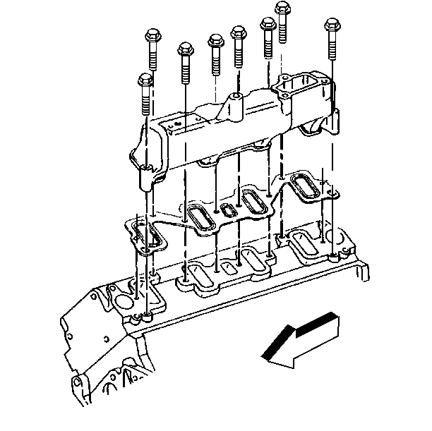
Notice: Use the correct fastener in the correct location. Replacement fasteners must be the correct part number for that application. Fasteners requiring replacement or fasteners requiring the use of thread locking compound or sealant are identified in the service procedure. Do not use paints, lubricants, or corrosion inhibitors on fasteners or fastener joint surfaces unless specified. These coatings affect fastener torque and joint clamping force and may damage the fastener. Use the correct tightening sequence and specifications when installing fasteners in order to avoid damage to parts and systems.
Important:
Tighten
Tighten the intake manifold studs, from the center out, to 42 N·m
(31 lb ft).
Tighten
Tighten the bracket nuts to 23 N·m (17 lb ft).
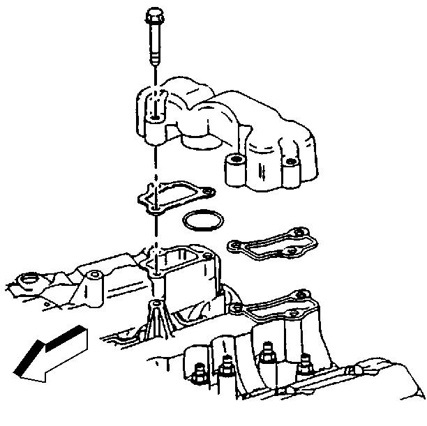
Tighten
Tighten the center intake manifold bolts to 23 N·m (17 lb ft).
Thermostat Housing
- Install the thermostat bypass connector.
- Install the thermostat bypass hose and clamps.
- Install the lower thermostat housing and gaskets.
- Install the bolts and stud/nut.
- Install the engine coolant temperature (ECT) sensor.
- Install the fuel bleed valve and stud/nut.
- Install the seals (3) onto the thermostats (2).
- Install the thermostats into the lower thermostat housing.
- Install the upper thermostat housing.
- Install the upper thermostat bolts/studs.
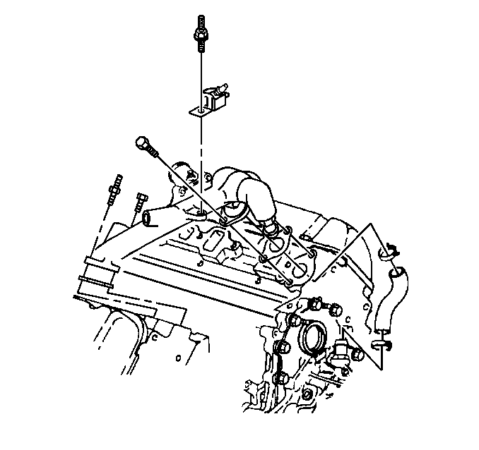
Notice: Use the correct fastener in the correct location. Replacement fasteners must be the correct part number for that application. Fasteners requiring replacement or fasteners requiring the use of thread locking compound or sealant are identified in the service procedure. Do not use paints, lubricants, or corrosion inhibitors on fasteners or fastener joint surfaces unless specified. These coatings affect fastener torque and joint clamping force and may damage the fastener. Use the correct tightening sequence and specifications when installing fasteners in order to avoid damage to parts and systems.
Tighten
Tighten the bolts and the stud/nut to 42 N·m (31 lb ft).
Tighten
Tighten the ECT to 23 N·m (17 lb ft).
Tighten
Tighten the stud/nut to 41 N·m (31 lb ft).
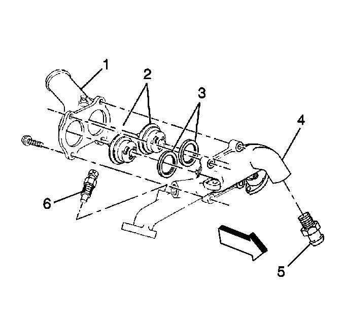
| • | The seals have a split, inner edge, which installs over the flange on the thermostats. |
| • | The seals have a bead on the surface that faces the water outlet. |
Tighten
Tighten the upper thermostat bolts/studs to 47 N·m (35 lb ft).
Intake Manifold Installation C3500HD
Lower Intake Manifold
- Install the lower intake manifold and gaskets.
- Install the intake manifold bolts/studs and fuel line clips.
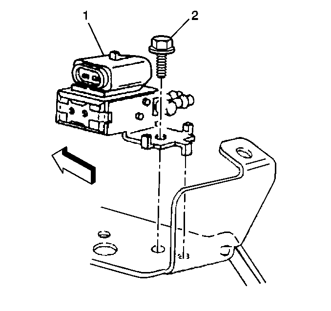
- Install the vacuum solenoid or solenoids (1).
- Install the vacuum solenoid bolt or bolts (2).
- Install the vacuum harness.
- Reconnect the vacuum harness hose connectors.
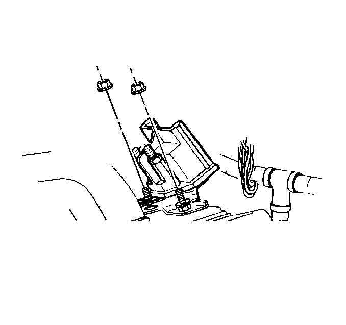
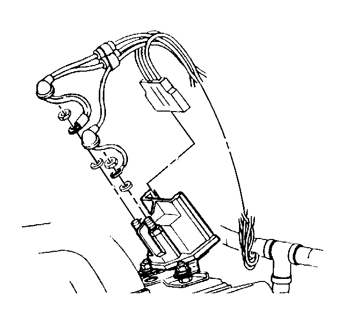
- Install the glow plug relay.
- Install the glow plug relay retaining nuts.
- Connect the glow plug relay electrical connectors.
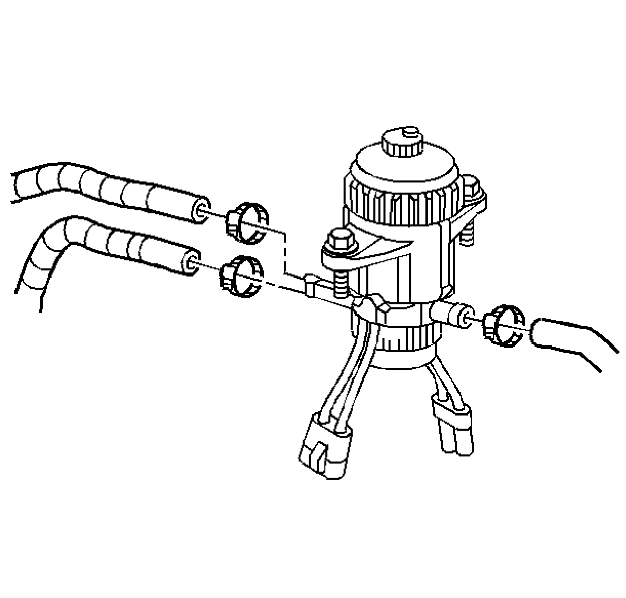
- Install the hoses and the clamps to the fuel filter assembly.
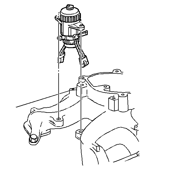
- Install the fuel filter assembly and the engine wiring harness bracket.
- Install the fuel filter mount bolts.
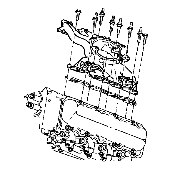
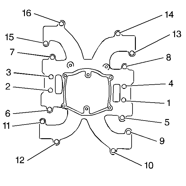
Notice: Use the correct fastener in the correct location. Replacement fasteners must be the correct part number for that application. Fasteners requiring replacement or fasteners requiring the use of thread locking compound or sealant are identified in the service procedure. Do not use paints, lubricants, or corrosion inhibitors on fasteners or fastener joint surfaces unless specified. These coatings affect fastener torque and joint clamping force and may damage the fastener. Use the correct tightening sequence and specifications when installing fasteners in order to avoid damage to parts and systems.
| • | Use teflon sealer to seal the four bolts, numbers 9, 11, 13 and 15 that are exposed to the crankcase. |
| • | Apply threadlocker GM P/N United States 12345493, GM P/N Canada 10953488, to the threads of the remaining bolts and studs. |
Tighten
Tighten the lower intake manifold bolts/studs, in sequence, to 42 N·m
(31 lb ft).
Tighten
Tighten the glow plug relay retaining nuts to 42 N·m (31 lb ft).
Tighten
Tighten the fuel filter mount bolts to 42 N·m (31 lb ft).
Upper Intake Manifold
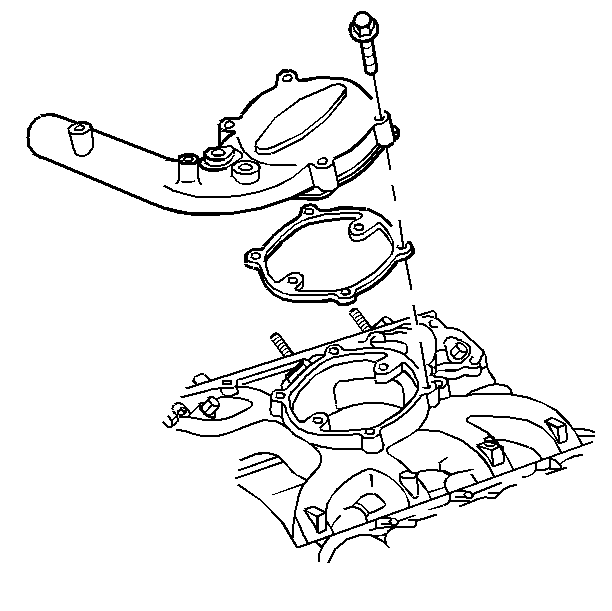
- Apply the silicone sealant GM P/N United States 12346240, GM P/N Canada 10953493, or equivalent to the turbocharger outlet.
- Install the upper intake manifold gasket.
- Slide the upper intake manifold into the turbocharger outlet hose.
- Install the upper intake manifold.
- Install the upper intake manifold bolts.
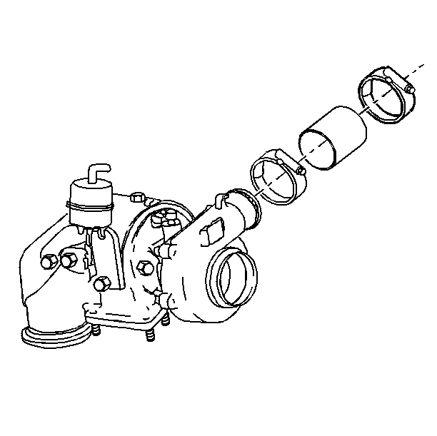
- Install the clamp for the turbocharger connector hose.
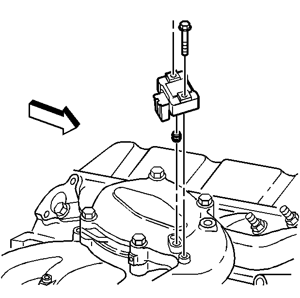
- Install the manifold absolute pressure (MAP) sensor gasket and MAP sensor.
- Install the MAP sensor retaining bolts.
- Connect the MAP sensor electrical connector.
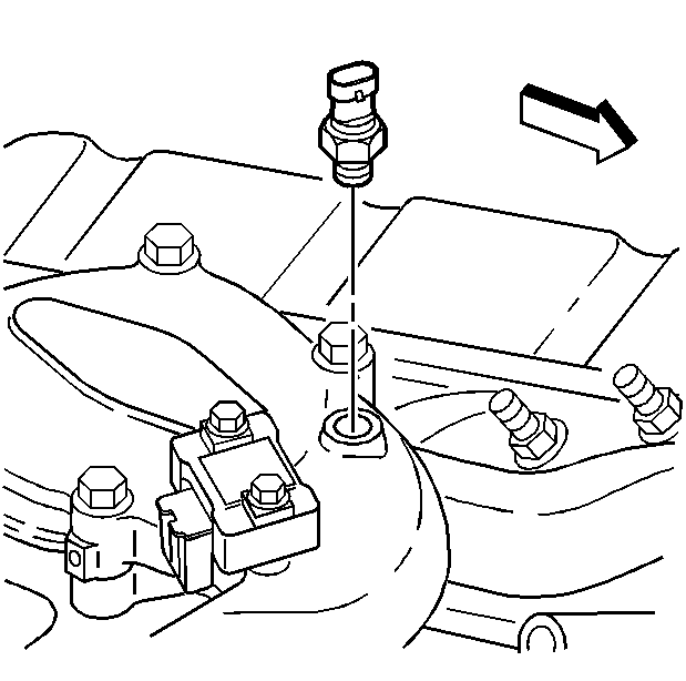
- Install the intake air temperature (IAT) sensor.
- Connect the IAT electrical connector.
Notice: Use the correct fastener in the correct location. Replacement fasteners must be the correct part number for that application. Fasteners requiring replacement or fasteners requiring the use of thread locking compound or sealant are identified in the service procedure. Do not use paints, lubricants, or corrosion inhibitors on fasteners or fastener joint surfaces unless specified. These coatings affect fastener torque and joint clamping force and may damage the fastener. Use the correct tightening sequence and specifications when installing fasteners in order to avoid damage to parts and systems.
Tighten
Tighten the upper intake manifold bolts to 23 N·m (17 lb ft).
Tighten
Tighten the connector hose clamps to 6 N·m (50 lb in).
Tighten
Tighten the MAP sensor retaining bolts to 2 N·m (16 lb in).
Tighten
Tighten the IAT sensor retaining to 23 N·m (17 lb ft).
Thermostat Housing
- Install the thermostat bypass connector.
- Install the thermostat bypass hose and clamps.
- Install the lower thermostat housing and gaskets.
- Install the bolts and stud/nut.
- Install the engine coolant temperature (ECT) sensor.
- Install the fuel bleed valve and stud/nut.
- Install the seals (3) onto the thermostats (2).
- Install the thermostats into the lower thermostat housing.
- Install the upper thermostat housing.
- Install the upper thermostat bolts/studs.

Notice: Use the correct fastener in the correct location. Replacement fasteners must be the correct part number for that application. Fasteners requiring replacement or fasteners requiring the use of thread locking compound or sealant are identified in the service procedure. Do not use paints, lubricants, or corrosion inhibitors on fasteners or fastener joint surfaces unless specified. These coatings affect fastener torque and joint clamping force and may damage the fastener. Use the correct tightening sequence and specifications when installing fasteners in order to avoid damage to parts and systems.
Tighten
Tighten the bolts and the stud/nut to 42 N·m (31 lb ft).
Tighten
Tighten the ECT to 23 N·m (17 lb ft).
Tighten
Tighten the stud/nut to 41 N·m (31 lb ft).

| • | The seals have a split, inner edge, which installs over the flange on the thermostats. |
| • | The seals have a bead on the surface that faces the water outlet. |
Tighten
Tighten the upper thermostat bolts/studs to 47 N·m (35 lb ft).
