For 1990-2009 cars only
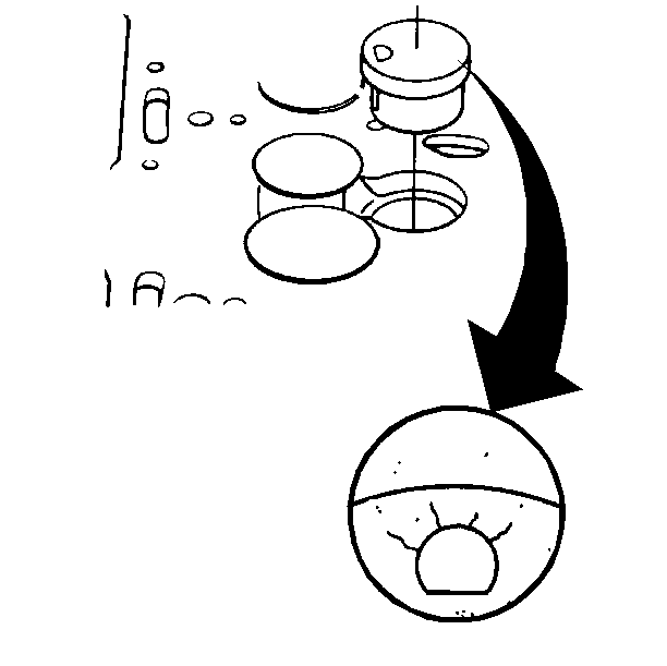
- Install the prechambers.
- Measure the valve protrusion for all valves (Valve protrusion is the distance the valve extends past, or is recessed into, the cylinder head surface.)
- Measure the prechamber installed depth.
- The prechamber should be flush to a maximum of 0.05 mm (0.002 in) protrusion.
- Lubricate the valve stems with engine oil.
- Install the valves.
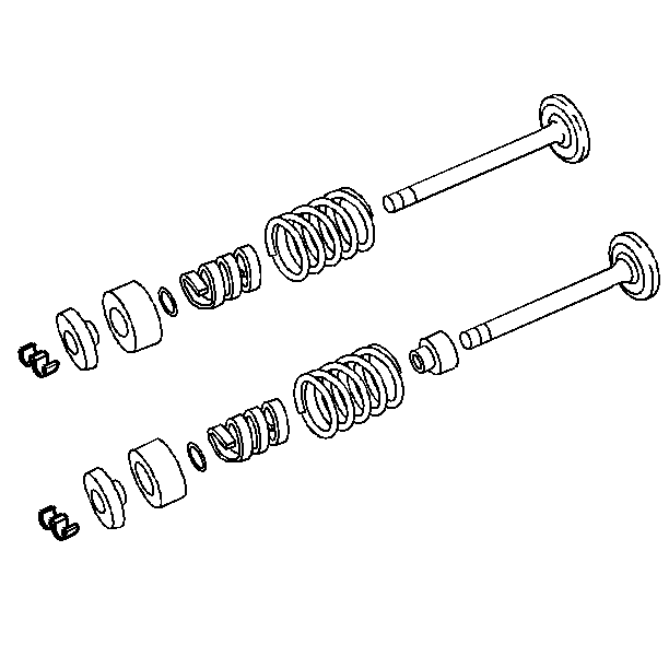
- Install the valve spring shims.
- Install the exhaust valve stem seals.
- Install the valve springs and dampers.
- Install the valve spring shields.
- Install the intake valve spring caps.
- Install the exhaust valve spring rotators.
- Install the valve stem O-ring seals and valve stem keys.
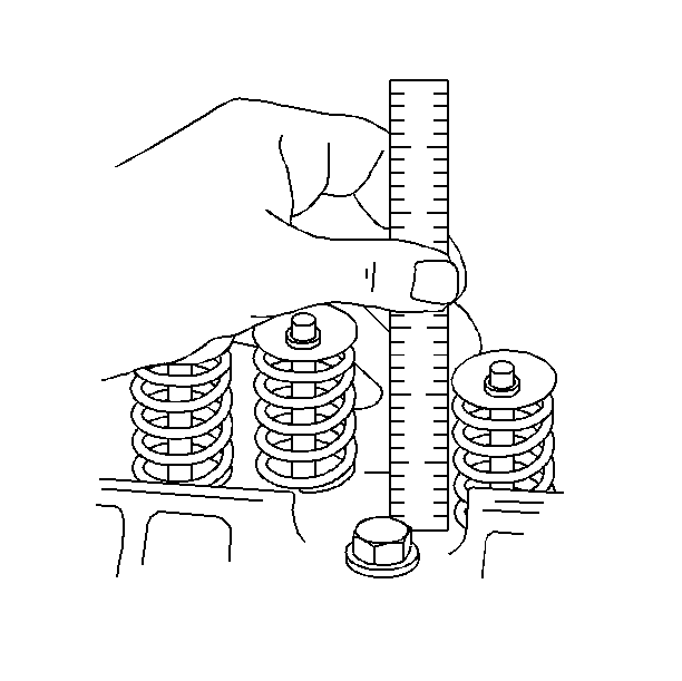
- Measure the valve spring installed height of each valve spring.

| 1.1. | Align the locating notch. The prechamber will fit correctly in only one position. |
| 1.2. | Using a 32 mm (1.25 in) socket, tap the prechamber into place. |
| 2.1. | With the plunger resting on the surface of the cylinder head, set the gage to zero. |
| 2.2. | Move the plunger over each valve and note the reading on the gage. |
| • | If the valve is recessed too deep, the valve pushrod can bottom out in the lifter and hold the valve open. When the valves are left open, the valve spring seat tension and cylinder compression are lost. |
| • | Maximum protrusion is negative 0.86 mm (negative 0.034 in) to negative 1.22 mm (negative 0.048 in) for both intake and exhaust valves. The valves are recessed. |
| • | Measure at two or more points on the prechamber where the prechamber seats on the head gasket shield and sealing ring. |
| • | Measure the difference between the flat surface of the prechamber and the flat surface of the cylinder head. |
| • | The prechamber must not protrude out of the cylinder head more than 0.05 mm (0.002 in). |
| • | The prechamber must not recess into the cylinder head. |

| • | Install the valve stem seals over the valve stems. |
| • | Seat the valve stem seals against the valve guides. |
| 13.1. | Compress the valve spring using the J 8062 Valve Spring Compressor. |
| 13.2. | Install a new O-ring seal on the valve stem's lower groove. |
| 13.3. | Apply a small amount of grease to the upper valve stem groove. |
| 13.4. | Assemble the two valve keys to the upper valve stem groove. Ensure that the keys seat properly in the groove. |
| 13.5. | Release the valve spring compressor, ensuring that the key stays in place. |
| 13.6. | Repeat this procedure for each remaining valve. |

| 14.1. | Using a narrow thin scale, measure the valve installed height from the spring seat in the cylinder head to the top of the valve spring cap. Refer to Engine Mechanical Specifications . |
| 14.2. | If the valve spring measurements exceed specifications, inspect for the following conditions: |
| • | Proper assembly |
| • | Excessive wear at the valve keys |
| • | Worn retainers |
| • | Worn valve key area on the valves |
| 14.3. | Install or remove valve spring seat shims between the spring and the cylinder head to obtain the desired measurement. NEVER shim the spring to give an installed height less than the specified amount. |
